Transistors: circuit, principle of operation, how bipolar and field-effect differ. Features of connecting devices to Arduino Bipolar transistor arduino
It will not be possible to connect a powerful load directly to the Arduino, for example a lighting lamp or an electric pump. The microcontroller does not provide the necessary power to operate such a load. The current that can flow through the Arduino outputs does not exceed 10-15 mA. A relay comes to the rescue, with which you can switch large currents. In addition, if the load is powered by alternating current, for example 220v, then there is no way to do without a relay. To connect powerful loads to Arduino via relays, relay modules are usually used.
Depending on the number of switched loads, one-, two-, three-, four- and more channel relay modules are used.
I bought mine, one and four channel modules, on Aliexpress, for $0.5 and $2.09, respectively.
Relay module design for Arduino, using the example of a 4-channel module HL-54S V1.0.
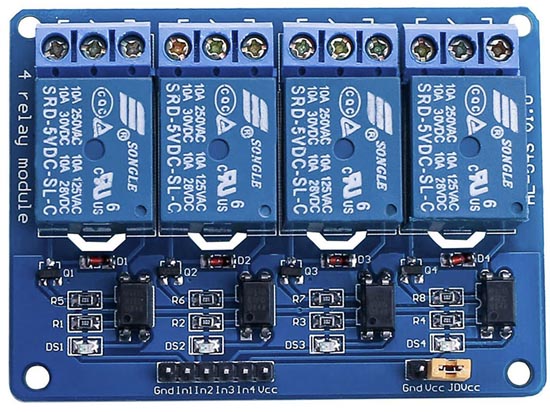
Let's take a closer look at the design of this module; all multi-channel modules are usually built according to this scheme.

Schematic diagram of the module.
To protect the Arduino pins from voltage surges in the relay coil, a J3Y transistor and an 817C optocoupler are used. Please note that the signal from the pin In supplied to the cathode of the optocoupler. This means that in order for the relay to close the contacts, you need to apply to the pinIn logical 0 (inverted signal).

There are also modules that have a signal from the pin In supplied to the anode of the optocoupler. In this case, you need to submit logical 1 per pinIn, to activate the relay.
The load power that modules can turn on/off is limited by the relays installed on the board.

In this case, electromechanical relays are used Songle SRD-05VDC-SL-C, having the following characteristics:
Operating voltage: 5 V
Coil operating current: 71 mA
Maximum switching current: 10A
Maximum switching DC voltage: 28 V
Maximum switching AC voltage: 250 V
Operating temperature: from -25 to +70°C

The Songle SRD-05VDC-SL-C relay has 5 contacts. 1 And 2 relay power supply. Contact group 3 And 4 are normally open contacts ( NO), contact group 3 And 5 - normally closed ( NC).
Similar relays come in different voltages: 3, 5, 6, 9, 12, 24, 48 V. In this case, a 5-volt version is used, which allows the relay module to be powered directly from the Arduino.
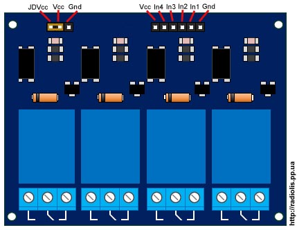
There is a jumper on the board ( JDVcc), to power the relay either from the Arduino or from a separate power supply.
Pinami In1,In2,In3,In4 The module is connected to the Arduino digital pins.
Connecting the relay of the HL-54S V1.0 module to Arduino.
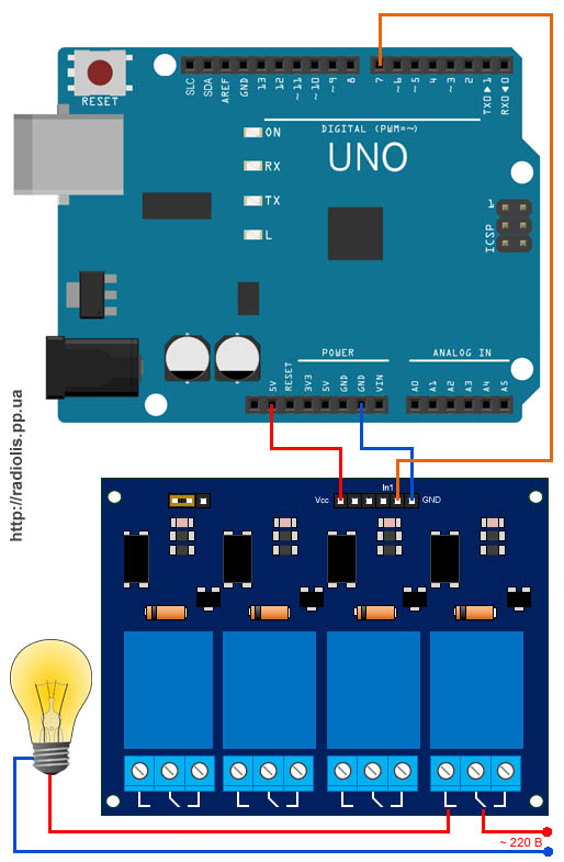
Since we have a module with 5-volt relays, we will connect it according to this scheme, taking the power from the Arduino itself. In the example, I will connect one relay; I will use a 220 V light bulb as a load.
To power the module relay from Arduino, the jumper must short-circuit the " Vcc" And " JDVcc", it is usually installed there by default.
If your relay is not 5 volt, you cannot power the module from Arduino; power must be taken from a separate source.
The diagram below shows how to connect power to the module from a separate source. Using this circuit, you need to connect a relay designed to be powered by more or less than 5 V. For 5-volt relays, this circuit will also be more preferable.

With this connection, you need to remove the jumper between the pins " Vcc" And " JDVcc" Next pin " JDVcc» connect to « + » external power supply, pin « Gnd» connect to « - » power supply. Pin " Gnd", which in the previous diagram was connected to the " Gnd"Arduino is not connected in this circuit. In my example, the external power supply is 5 V, if your relay is designed for a different voltage (3, 12, 24 V), select the appropriate external power supply.
Sketch for controlling a relay module via Arduino.
Let's upload a sketch to Arduino that will turn the light bulb (flashing light) on and off.
| int relayPin = 7; void setup() ( void loop() ( |
In line int relayPin = 7; indicate the number of the Arduino digital pin to which the pin was connected In1
module relay. You can connect to any digital pin and indicate it in this line.
In line delay(5000); You can change the time value at which the light will be on and at which it will be extinguished.
In line digitalWrite(relayPin, LOW); indicated when applying a logical zero ( LOW), the relay module will close the contacts and the light will light.
In line digitalWrite(relayPin, HIGH); indicated when submitting a logical unit ( HIGH), the relay module will open the contacts and the light will go out.
As we see, in the line digitalWrite(relayPin, LOW); left the parameter LOW. If the relay closes its contacts and the light comes on, it means the pin In1 you need to supply a logical zero, like mine. If the light does not light up, upload a sketch in which we replace the parameter LOW on HIGH.
The result of the sketch on video.
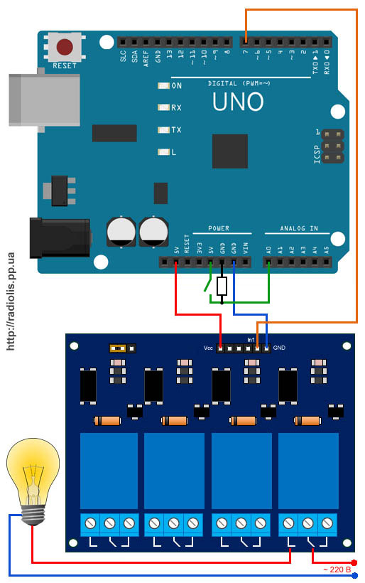
Now let's add a tact button to the circuit and when you press it, the relay module will turn on the light bulb.

We connect the button together with a 10k pull-up resistor, which will not allow external interference to affect the operation of the circuit.
Uploading the sketch
In line if(digitalRead(14)==HIGH) set the number of the digital pin on which the button is connected. You can connect to any free one. In the example this is an analog pinA0, it can also be used as a digital 14 pin.
In line delay(300); the value is specified in milliseconds. This value indicates how long after pressing or releasing the button, actions must be performed. This is protection against contact bounce.
For information! All analog inputsfrom A0 ( numbered as 14) to A5 (19), can be used as digital ( Digital PWM).
In conclusion, the result of the sketch is shown in the video.
Cheaper relay modules may not contain an optocoupler in their circuit, as for example in my case with a single-channel module.

Scheme of a single-channel relay module. The manufacturer saved on the optocoupler, which is why the Arduino board lost its galvanic isolation. To operate such a board, on the pin In you need to supply a logical zero.
Connecting the module relay to the Arduino Due.
The Arduino Due operates at 3.3 volts, which is the maximum voltage it can have across its inputs/outputs. If there is a higher voltage, the board may burn out.
The question arises, how to connect the module to the relay?

Remove the JDVcc jumper. Connect the pin " Vcc» on the module relay board to the pin "3.3V» Arduino. If the relay is designed for 5 volts, connect the pin “ GND» module relay boards, with pin « GND» Arduino Due. Pin " JDVcc"connect to pin" 5V"on the Arduino Due board. If the relay is designed for a different voltage, then we connect the power to the relay as in the figure, in the example it is 5 volts. If you have a multi-channel relay module, please check that « JDVcc" connected to one side of all relays. The optocoupler is activated by a 3.3V signal, which in turn activates the transistor used to turn on the relay.
Solid state relay made from a triac for switching a powerful load via Arduino
We looked at working with a photoresistor to control LEDs. However, it is often necessary to control a more powerful load, such as an incandescent lamp, electric motor, electromagnet, etc. Arduino outputs cannot supply power to such a powerful load and high voltage. For example, in robotics, 12V, 24V, 36V, etc. motors are often used. In addition, the output current of the Arduino pin is usually limited to 40 mA.
One way to control a powerful load is to use MOSFET transistors. This makes it possible to connect a fairly powerful load with a supply voltage of 40-50 volts or more and currents of several amperes, say electric motors, electromagnets, halogen lamps, and so on.
The connection diagram is quite simple, as you can see.
If the load is inductive (electric motor, solenoid valve, etc.), then it is recommended to install a protective diode that will protect the mosfet from self-induction voltage. If you control an electric motor using PWM without a protection diode, then problems may arise such as the mosfet heating up or flying out, your motor will spin slowly, power loss will occur, etc. So always install a protection diode for inductive loads. The protective diode built into the mosfet in most cases does not protect against inductive emissions!
If your load is active - LED, halogen lamp, heating element, etc., then in this case a diode is not needed.
It is advisable to install a Pull-Down resistor in the gate circuit (pulling resistor between the gate and source). It is necessary to ensure that the mosfet gate maintains a low level in the absence of a high level signal from the Arduino. This prevents the transistor from turning on spontaneously.
When selecting a mosfet, so that it opens directly from the microcontroller and does not need to place bipolar transistors and drivers in front of it, pay attention to the Gate Threshold parameter, which should be approximately from 1 to 4 Volts. Often such transistors are labeled asLogic Level.
Let's take a transistor for example: IRL3705N N-Channel Hexfet Power MOSFET.
This transistor is capable of withstanding continuous current up to 89A (naturally with a heat sink) and opens at a gate voltage of 1V (parameter V GS(th)). Therefore, we can directly connect this transistor to the Arduino legs. When the transistor is fully open, the Source-Drain resistance is only 0.01 Ohm (parameter R DS(on)). Therefore, if you connect a 12V, 10A electric motor to it, the voltage drop on the transistor will be only 0.1V, and the power dissipation will be 1 Watt.
If we use the PWM output of the controller, we can control the power (and therefore the rotation speed) of the motor.
The following articles will include devices that need to control external loads. By external load I mean everything that is attached to the legs of the microcontroller - LEDs, light bulbs, relays, motors, actuators... well, you get the idea. And no matter how hackneyed this topic may be, in order to avoid repetition in the following articles, I still risk not being original - you will forgive me :). I will briefly, in recommendatory form, show the most common ways to connect the load (if you want to add something, I will be only too glad).
Let’s immediately agree that we are talking about a digital signal (a microcontroller is still a digital device) and we will not deviate from the general logic: 1
- included, 0
-off. Let's begin.
DC loads include: LEDs, lamps, relays, DC motors, servos, various actuators, etc. Such a load is most simply (and most often) connected to a microcontroller.
1.1 Connection loads through a resistor.
The simplest and probably most often used method when it comes to LEDs.

A resistor is needed in order to limit the current flowing through the microcontroller leg to permissible 20mA. It is called ballast or damping. You can approximately calculate the resistor value by knowing the load resistance Rн.
Rquenching =(5v / 0.02A) – Rн = 250 – Rн
As you can see, even in the worst case, when the load resistance is zero, 250 Ohms is enough to ensure that the current does not exceed 20 mA. This means that if you don’t want to count something there, put 300 Ohm and you will protect the port from overload. The advantage of the method is obvious - simplicity.
1.2 Connection loads using a bipolar transistor.
If it so happens that your load consumes more than 20mA, then, of course, a resistor will not help here. You need to somehow increase (read strengthen) the current. What is used to amplify the signal? Right. Transistor!
![]()
It is more convenient to use for strengthening n-p-n transistor connected according to the circuit OE. With this method, you can connect a load with a higher supply voltage than the power supply to the microcontroller. The resistor on the base is limiting. Can vary within wide limits (1-10 kOhm), in any case the transistor will operate in saturation mode. The transistor can be anything n-p-n transistor. The gain is practically irrelevant. The transistor is selected based on the collector current (the current we need) and the collector-emitter voltage (the voltage that powers the load). Power dissipation also matters - so as not to overheat.
Of the common and easily accessible ones, you can use BC546, BC547, BC548, BC549 with any letters (100mA), and even the same KT315 will do (those who have leftovers from old stocks).
- Datasheet for bipolar transistor BC547
1.3 Connection loads using a field effect transistor.
Well, what if the current of our load is within ten amperes? It will not be possible to use a bipolar transistor, since the control currents of such a transistor are large and will most likely exceed 20 mA. The output can be either a composite transistor (read below) or a field-effect transistor (aka MOS, aka MOSFET). The field-effect transistor is simply a wonderful thing, since it is controlled not by current, but by potential at the gate. This makes it possible for microscopic gate current to control large load currents.
Any n-channel field-effect transistor is suitable for us. We choose, like bipolar, by current, voltage and power dissipation.

When turning on a field-effect transistor, you need to consider a number of points:
- since the gate is, in fact, a capacitor, when the transistor switches, large currents flow through it (short-term). In order to limit these currents, a limiting resistor is placed in the gate.
— the transistor is controlled by low currents and if the output of the microcontroller to which the gate is connected is in a high-impedance Z-state, the field switch will begin to open and close unpredictably, catching interference. To eliminate this behavior, the microcontroller leg must be “pressed” to the ground with a resistor of about 10 kOhm.
The field-effect transistor, against the background of all its positive qualities, has a drawback. The cost of controlling low current is the slowness of the transistor. Of course, it will handle PWM, but if the permissible frequency is exceeded, it will respond to you with overheating.
1.4 Connection loads using a compound Darlington transistor.
An alternative to using a field-effect transistor for high-current loads is to use a composite Darlington transistor. Externally, it is the same transistor as, say, a bipolar one, but internally a pre-amplifier circuit is used to control the powerful output transistor. This allows low currents to drive a powerful load. The use of a Darlington transistor is not as interesting as the use of an assembly of such transistors. There is such a wonderful microcircuit as ULN2003. It contains as many as 7 Darlington transistors, each of which can be loaded with a current of up to 500 mA, and they can be connected in parallel to increase the current.

The microcircuit is very easy to connect to the microcontroller (just pin to pin), has convenient wiring (input opposite output) and does not require additional wiring. As a result of this successful design, ULN2003 is widely used in amateur radio practice. Accordingly, it will not be difficult to get it.
- Datasheet for Darlington assembly ULN2003
If you need to control AC devices (most often 220v), then everything is more complicated, but not much.
2.1 Connection loads using a relay.
The simplest and probably most reliable connection is using a relay. The relay coil itself is a high-current load, so you cannot connect it directly to the microcontroller. The relay can be connected via a field-effect or bipolar transistor, or via the same ULN2003, if several channels are needed.

The advantages of this method are high switching current (depending on the selected relay), galvanic isolation. Disadvantages: limited speed/frequency of activation and mechanical wear of parts.
It makes no sense to recommend something for use - there are many relays, choose according to the required parameters and price.
2.2 Connection loads using a triac (triac).
If you need to control a powerful AC load, and especially if you need to control the power supplied to the load (dimers), then you simply cannot do without using a triac (or triac). The triac is opened by a short current pulse through the control electrode (for both negative and positive voltage half-waves). The triac closes itself when there is no voltage on it (when the voltage passes through zero). This is where the difficulties begin. The microcontroller must control the moment the voltage crosses zero and, at a precisely defined moment, send a pulse to open the triac - this is a constant controller occupancy. Another difficulty is the lack of galvanic isolation in the triac. You have to do it on separate elements, complicating the circuit.

Although modern triacs are controlled by a fairly low current and can be connected directly (via a limiting resistor) to a microcontroller, for safety reasons they have to be switched on through optical decoupling devices. Moreover, this applies not only to the triac control circuits, but also to the zero control circuits. 
A rather ambiguous way to connect the load. Since, on the one hand, it requires the active participation of a microcontroller and a relatively complex circuit design. On the other hand, it allows you to manipulate the load very flexibly. Another disadvantage of using triacs is the large amount of digital noise created during their operation - suppression circuits are needed.
Triacs are quite widely used, and in some areas they are simply irreplaceable, so getting them is not a problem. Triacs of the BT138 type are very often used in amateur radio.
Sometimes there comes a time when the user wants to control a powerful device using . We all know that Arduino can output 20mA (maximum 40mA) on each of its outputs. Okay, but what to do when we want to control, for example, a DC motor.
In this case we can use, for example, a bipolar transistor, if the current is not too large, an L293D bridge or a MOSFET transistor.
What is a MOSFET?
In our project we will use the STP16NF06L MOSFET transistor, which has an N-type channel.
MOSFET is a field effect transistor that has 3 legs: source (S), gate (G) and drain (D). Current flows between the source and drain, through the so-called channel. The amount of current flowing depends on the control voltage applied to the gate - source.
MOSFET transistors are faster than bipolar transistors, since the processes occurring in them are purely electrostatic. The main factor influencing switching time is the presence of gate capacitance.
Connecting MOSFET to Arduino
The gate (G) of the MOSFET transistor must be connected to the Arduino. In general, we can say that the source (S) should be connected to the negative of our circuit, and the drain (D) should be connected to the negative of our object that we are going to control (for example, a light bulb, a motor). In addition to this, it is worth connecting a resistor between the gate (G) and source (S). This will give us confidence that the gate will be low when there is no control signal from the Arduino.
Moreover, in the event that we have a cable failure, we will have the confidence that there will be no undefined state at the gate that could cause the controlled object to turn on and off.
In our case, we will use a DC motor for control. Our circuit is designed to increase and decrease the engine speed.
We connect everything as shown below. In addition, you can connect an external power source, not forgetting the grounds of the power supply and Arduino to connect to each other.

The transistor is a ubiquitous and important component in modern microelectronics. Its purpose is simple: it allows you to control a much stronger one using a weak signal.
In particular, it can be used as a controlled “damper”: by the absence of a signal at the “gate”, block the flow of current, and by supplying it, allow it. In other words: this is a button that is pressed not by a finger, but by applying voltage. This is the most common application in digital electronics.
Transistors are available in different packages: the same transistor can look completely different in appearance. In prototyping, the most common enclosures are:
TO-92 - compact, for light loads
TO-220AB - massive, good heat dissipation, for heavy loads
The designation on the diagrams also varies depending on the type of transistor and the designation standard used in the compilation. But regardless of the variation, its symbol remains recognizable.
Bipolar transistors
Bipolar junction transistors (BJT, Bipolar Junction Transistors) have three contacts:
Collector - high voltage is applied to it, which you want to control
Base - a small amount is supplied through it current to unlock large; the base is grounded to block it
Emitter - current flows through it from the collector and base when the transistor is “open”
![]()
The main characteristic of a bipolar transistor is the indicator hfe also known as gain. It reflects how many times more current in the collector-emitter section the transistor can pass in relation to the base-emitter current.
For example, if hfe= 100, and 0.1 mA passes through the base, then the transistor will pass through itself a maximum of 10 mA. If in this case there is a component in the high current section that consumes, for example, 8 mA, it will be provided with 8 mA, and the transistor will have a “reserve”. If there is a component that draws 20 mA, it will only be provided with the maximum 10 mA.
Also, the documentation for each transistor indicates the maximum permissible voltages and currents at the contacts. Exceeding these values leads to excessive heating and reduced service life, and a strong excess can lead to destruction.
NPN and PNP
![]()
The transistor described above is a so-called NPN transistor. It is called that because it consists of three layers of silicon connected in the order: Negative-Positive-Negative. Where negative is a silicon alloy with an excess of negative charge carriers (n-doped), and positive is an alloy with an excess of positive charge carriers (p-doped).
NPNs are more effective and common in industry.
When designating PNP transistors, they differ in the direction of the arrow. The arrow always points from P to N. PNP transistors have an “inverted” behavior: current is not blocked when the base is grounded and blocked when current flows through it.
Field effect transistors
Field effect transistors (FET, Field Effect Transistor) have the same purpose, but differ in internal structure. A particular type of these components are MOSFET (Metal-Oxide-Semiconductor Field Effect Transistor) transistors. They allow you to operate with much greater power with the same dimensions. And the control of the “damper” itself is carried out exclusively using voltage: no current flows through the gate, unlike bipolar transistors.
Field effect transistors have three contacts:
Drain - high voltage is applied to it, which you want to control
Gate - voltage is applied to it to allow current to flow; the gate is grounded to block the current.
Source - current flows through it from the drain when the transistor is “open”
![]()
N-Channel and P-Channel
![]()
By analogy with bipolar transistors, field-effect transistors differ in polarity. The N-Channel transistor was described above. They are the most common.
P-Channel when designated differs in the direction of the arrow and, again, has an “inverted” behavior.
Connecting transistors to drive high-power components
A typical task of a microcontroller is to turn a specific circuit component on and off. The microcontroller itself usually has modest power handling characteristics. So Arduino, with 5 V output per pin, can withstand a current of 40 mA. Powerful motors or ultra-bright LEDs can draw hundreds of milliamps. When connecting such loads directly, the chip can quickly fail. In addition, for the operation of some components, a voltage greater than 5 V is required, and Arduino cannot produce more than 5 V from the digital output pin.
But it is easily enough to control a transistor, which in turn will control a large current. Let's say we need to connect a long LED strip that requires 12 V and consumes 100 mA:
![]()
Now, when the output is set to logical one (high), the 5 V entering the base will open the transistor and current will flow through the tape - it will glow. When the output is set to logic zero (low), the base will be grounded through the microcontroller and current flow will be blocked.
Pay attention to the current limiting resistor R. It is necessary so that when control voltage is applied, a short circuit does not form along the route microcontroller - transistor - ground. The main thing is not to exceed the permissible current through the Arduino contact of 40 mA, so you need to use a resistor with a value of at least:
Here Ud- this is the voltage drop across the transistor itself. It depends on the material from which it is made and is usually 0.3 – 0.6 V.
But it is absolutely not necessary to keep the current at the permissible limit. It is only necessary that the gain of the transistor allows you to control the required current. In our case it is 100 mA. Acceptable for the transistor used hfe= 100, then a control current of 1 mA will be enough for us
A resistor with a value from 118 Ohm to 4.7 kOhm is suitable for us. For stable operation on one side and light load on the chip on the other, 2.2 kOhm is a good choice.
If you use a field-effect transistor instead of a bipolar transistor, you can do without a resistor:
![]()
This is due to the fact that the gate in such transistors is controlled solely by voltage: there is no current in the microcontroller - gate - source section. And due to its high characteristics, a circuit using MOSFETs allows you to drive very powerful components.