RGB lamp with remote control circuit diagram. Connecting RGB LED strips. Lack of addressable LEDs
Now let's look at the multicolor LED, which is often called in abbreviation: RGB LED. RGB is an abbreviation that stands for: Red - red, Green - green, Blue - blue. That is, three separate LEDs are placed inside this device. Depending on the type, an RGB LED may have a common cathode or a common anode.
1. Mixing colors
Why is an RGB LED better than three conventional ones? It's all about the ability of our vision to mix light from different sources placed close to each other. For example, if we place blue and red LEDs next to each other, then at a distance of several meters their glow will merge and the eye will see one purple dot. And if we also add green, the dot will appear white to us. This is exactly how computer monitors, televisions and outdoor screens work. The TV matrix consists of individual dots of different colors. If you take a magnifying glass and look through it at the switched on monitor, you can easily see these dots. But on an outdoor screen, the dots are not placed very densely, so that they can be distinguished with the naked eye. But from a distance of several tens of meters these points are indistinguishable. It turns out that the closer the multi-colored dots are to each other, the less distance the eye needs to mix these colors. Hence the conclusion: unlike three separate LEDs, the color mixing of an RGB LED is noticeable already at a distance of 30-70 cm. By the way, an RGB LED with a matte lens performs even better.2. Connecting an RGB LED to Arduino
Since the multicolor LED consists of three regular LEDs, we will connect them separately. Each LED is connected to its own pin and has its own separate resistor. In this tutorial we are using an RGB LED with a common cathode, so there will only be one wire to ground. Schematic diagram Layout appearance
3. Program for controlling an RGB LED
Let's create a simple program that will light each of the three colors in turn. const byte rPin = 3; const byte gPin = 5; const byte bPin = 6; void setup() ( pinMode(rPin, OUTPUT); pinMode(gPin, OUTPUT); pinMode(bPin, OUTPUT); ) void loop() ( // turn off blue, turn on red digitalWrite(bPin, LOW); digitalWrite(rPin, HIGH); delay(500); // turn off red, turn on green digitalWrite(rPin, LOW); digitalWrite(gPin, HIGH); delay(500); // turn off green, turn on blue digitalWrite(gPin, LOW); digitalWrite( bPin, HIGH); delay(500); ) Load the program onto Arduino and observe the result. Your browser does not support the video tag. Let's optimize the program a little: instead of the variables rPin, gPin and bPin, we will use an array. This will help us in the next tasks. const byte rgbPins = (3,5,6); void setup() ( for(byte i=0; i<3; i++) pinMode(rgbPins[i], OUTPUT); } void loop() { digitalWrite(rgbPins, LOW); digitalWrite(rgbPins, HIGH); delay(500); digitalWrite(rgbPins, LOW); digitalWrite(rgbPins, HIGH); delay(500); digitalWrite(rgbPins, LOW); digitalWrite(rgbPins, HIGH); delay(500); }4. Seven colors of the rainbow
Now let's try to light two colors at the same time. Let's program the following sequence of colors:- red
- red + green = yellow
- green
- green + blue = light blue
- blue
- blue + red = purple
5. Smooth color change
It was not for nothing that we connected the RGB LED to pins 3, 5 and 6. As you know, these pins allow you to generate a PWM signal of different duty cycles. In other words, we can not just turn the LED on or off, but control the voltage level on it. This is done using the function analogWrite. Let's make sure that our LED will transition between the colors of the rainbow not abruptly, but smoothly. const byte rgbPins = (3,5,6); int dim = 1; void setup() ( for(byte i=0; i<3; i++){ pinMode(rgbPins[i], OUTPUT); } // начальное состояние - горит красный цвет analogWrite(rgbPins, 255); analogWrite(rgbPins, 0); analogWrite(rgbPins, 0); } void loop() { // гасим красный, параллельно разжигаем зеленый for(int i=255; i>=0; i--)( analogWrite(rgbPins, i/dim); analogWrite(rgbPins, (255-i)/dim); delay(10); ) // turn off green, turn on blue in parallel for(int i=255; i> =0; i--)( analogWrite(rgbPins, i/dim); analogWrite(rgbPins, (255-i)/dim); delay(10); ) // turn off blue, turn on red in parallel for(int i=255 ; i>=0; i--)( analogWrite(rgbPins, i/dim); analogWrite(rgbPins, (255-i)/dim); delay(10); ) ) The dim variable determines the brightness of the glow. At dim = 1 we have maximum brightness. Load the program onto Arduino. Your browser does not support the video tag.Tasks
- Temperature indicator. Let's add a thermistor to the circuit and connect it to the analog input. The LED should change color depending on the temperature of the thermistor. The lower the temperature, the bluer the color, and the higher the temperature, the more red.
- RGB lamp with regulator. Let's add three variable resistors to the circuit and connect them to the analog inputs. The program should continuously read the resistor values and change the color of the corresponding RGB LED component.
Glowing only in red - R, green - G, blue - B or white - CW, as a rule, they are connected directly to a 12 V or 24 V DC source. R G B LED strip, like monochrome ones, can also be connected to a DC power supply current by connecting terminals R, G and B to each other.
But in this case, the opportunity to implement the color lighting effects for which the tape was created will be missed. Therefore, when installing colored LED strips, an electronic controller is usually installed in the open circuit between the power supply and the strip. It allows you to automatically change the color and brightness of the tape in a dynamic mode according to a program specified from the remote control.
The photo shows an electrical diagram for connecting an R G B LED strip to a 220 V network. The power supply (adapter) converts an alternating voltage of 220 V into a direct current voltage of 12 V, which is supplied to the R G B controller via two wires, maintaining polarity. An LED strip is connected to the controller via four wires in accordance with the markings. For ease of installation and repair of LED lighting, the units are connected to each other using connectors.
Electrical circuit of LED R G B LED SMD-5050
To connect, and even more so repair, an R G B LED strip at a professional level, you need to understand how it works and know the electrical circuit and pinout of the LEDs used in the strips. The photo below shows a fragment of an R G B LED strip with a printed wiring diagram for LED crystals.

As can be seen in the diagram, the crystals in the LED are not electrically connected to each other. Three multi-colored crystals in one LED housing form a triad. Thanks to this design, by controlling the brightness of each crystal individually, you can obtain an infinite number of LED glow colors. The displays of cell phones, navigators, cameras, computer monitors, televisions and many other products are built on this principle of color management.
Technical characteristics of the SMD-5050 LED are given on the website page “Handbook of SMD LEDs”.
Electrical circuit of LED R G B strip on SMD-5050 LEDs
Having understood the design of the LED, it is easy to understand the design of the LED strip. At the top of the picture is a photograph of a working section of LED R G B strip, and at the bottom is its electrical circuit.

As can be seen from the diagram, the contact pads of the same name on the LED strip, located on its right and left sides, are electrically connected directly to each other. Thus, it is possible to supply power voltage to the tape from either end and to the next section of the tape when it is extended.
LED crystals VD1, VD2 and VD3 of the same glow color are connected in series. To limit the current, current-limiting resistors are installed in each of the color circuits. Two of them are rated 150 ohms, and one is 300 ohms, in a red crystal chain. A resistor of a larger value is installed to equalize the brightness of all colors, taking into account the intensity of radiation from the LED crystal and the different color sensitivity of the human eye to different colors.
How to cut LED strip into pieces
As you probably already understood, R G B LED strip of any length (this also applies to monochrome strips) consists of short independent segments that represent a finished product. It is enough to apply supply voltage to the contact pads and the tape will emit light. To obtain a piece of tape of the required length, elementary sections are connected to each other in accordance with the letter marking.

Typically the tape is produced in a length of five meters. If necessary, it can be shortened by cutting crosswise along a line drawn in the center of the contact pads between the markings; sometimes, in this place, a symbolic image of scissors is additionally applied. Sometimes the tape has to be cut to install at an angle. In this case, the cut contact pads of the same name are connected to each other by soldering with pieces of wire.
Ways to control glow color
R G B LED strips
There are two ways to control the color mode of an R G B LED strip, using three switches or an electronic device.
The principle of operation of the simplest controller on switches
Let's look at the operating principle of the simplest controller, based on mechanical switches. As a switch for manually controlling the glow of the R G B tape, you can use a three-key wall switch, designed to turn on chandeliers and lamps in a 220 V household network. The electrical connection diagram will then look like this.

Resistors R1-R3 serve to limit the current and can be installed anywhere in the power supply circuit for crystals of the same color. Using this scheme, you can connect R G B tapes designed for a supply voltage of both 12 V and 24 V.
As can be seen from the diagram, the positive terminal of the power supply is connected directly to the positive terminal of the LED strip, which is common to LEDs of all colors, and the negative terminal is connected to the R, G and B contacts of the strip through a switch. Using a switch of three switches, you can get seven colors of tape glow. This is the simplest, most reliable and cheapest way to control the glow colors of an R G B tape.
Operating principle of the electronic controller
To obtain an infinite number of glow colors of the R G B tape and in automatic mode dynamically change the value of the luminous flux, instead of switches, an electrical unit is used, which is called an R G B controller. It is included in the open circuit between the power supply and the R G B tape. Typically, the controller kit includes a remote control that allows you to remotely control its operating mode, and as a result, the lighting mode of the LED strip.
Since the operation of an LED strip usually requires a DC voltage of 12 V (less often 24 V), to connect it to a 220 V AC power supply, a power supply or adapter is used that converts AC voltage into DC voltage, which is connected through a detachable connection supplied to the controller unit.

Let's look at the operating principle of an RGB controller using the example of the simplest and most widely used controller, model LN-IR24. It consists of three functional units - an RGB control controller, power switches and an infrared sensor chip (IR). The controller chip is programmed with the required operating algorithm for the LED strip. The controller chip is controlled by a signal coming from the IR sensor chip. The IR sensor receives a control signal when you press buttons on the remote control.
The supply voltage to the LED strip is controlled using three field-effect transistors operating in switching mode. When a signal from the RGB control controller IC reaches the gate of the transistor, its drain-source junction opens and current begins to flow through the LEDs, causing them to emit light. The brightness of the LEDs is controlled by high-frequency changes in the pulse width of the supplied supply voltage (pulse width modulation).
Selecting a power supply and controller for R G B tape
The power supply for the RGB LED strip must be selected based on its supply voltage and current consumption. The most popular are LED strips for a DC voltage of 12 V. Current consumption in circuits R, G and B can be found from the label or determined independently using the reference data for LEDs presented in the table on the site page Reference table of parameters of popular SMD LEDs. It is customary to indicate the power consumption of a tape per meter of its length.
Let's look at an example of how to determine the power consumption of an RGB strip of an unknown type for a supply voltage of 12 V. For example, you need to select a power supply and controller for an RGB strip 5 m long. The first thing you need to do is determine the type of RGB LEDs installed on the strip. To do this, just measure the size of the sides of the LED. Let's say it turns out to be 5 mm × 5 mm. From the table we determine that this size is for an LED of the LED-RGB-SMD5050 type. Next you need to count the number of LED housings per meter of length. Let's say there are 30 pieces.
One LED crystal consumes a current of 0.02 A, three crystals are placed in one case, therefore the total current consumption of one LED will be 0.06 A. There are 30 LEDs per meter of length, multiply the current by the amount 0.06 A × 30 = 1.8 A. But the diodes are connected three in series, which means that the real current consumption of a meter of tape will be three times less, that is, 0.6 A. The length of our tape is five meters, therefore, the total current consumption will be 0.6 A × 5 m = 3 A.

Calculations have shown that to power an R G B tape five meters long, you need a power supply or network adapter with a DC output voltage of 12 V and a load current of at least 3 A. The power supply must have a current reserve, so an adapter model APO12-5075UV was selected, designed for a load current of up to 5 A. When choosing a power supply, you need to take into account that its output connector must match the R G B connector of the controller.
When choosing a controller, it is necessary to take into account that the current consumption in a single channel R, G or B will be three times less. Therefore, for our case, we need to take a controller designed for a voltage of 12 V and a maximum permissible load current per channel of at least 3 A/3=1 A.

For example, the LN-IR24B R G B controller meets these requirements. It is designed for a load current of up to 2 A (you can connect up to 10 meters of RGB tape). Allows you to turn the tape on and off, select 16 static colors and 6 dynamic modes remotely, from a distance of up to eight meters, using an elegant remote control. The supply voltage to the controller is supplied from the power supply or network adapter using a coaxial DC Jack. R G B controller LN-IR24B is lightweight and has small overall dimensions.

The appearance of the LED strip lighting kit prepared based on the calculation results is shown in the photograph. The kit includes a power supply model APO12-5075UV, R G B controller LN-IR24B with remote control and R G B LED strip.

If you need to connect several five-meter R G B strips, you will need a more powerful controller, for example, CT305R, which allows you to supply current up to 5 A to LEDs of the same color. This controller can be controlled not only using a remote control, but also via a network from a computer, thereby turning R G B lighting into color and musical accompaniment when listening to music.
It is unacceptable to connect LED strips longer than five meters in series, since the current-carrying paths of the strip itself have a small cross-section. Such a connection will lead to a decrease in the luminous flux on a section of tape exceeding a length of five meters. If you need to connect several five-meter LED strips, then the conductors of each of them are connected directly to the controller.
In powerful models of controllers, terminal blocks are used to connect external devices, in which the wires are clamped with a screw. There must be markings next to the terminals. INPUT (IN) means input; an external power supply is connected to these terminals, from which the supply voltage is supplied for the controller itself and the LED strips. Polarity is indicated by additional signs “+” and “-”. Failure to observe the correct polarity when connecting the power supply may damage the controller.
The group of terminals for connecting R G B tape is marked OUTPUT (OUT) and means output. The colors are designated by the letters R (red), G (green), B (blue) and V+ (this is the common wire of any other color). Colored wires usually come from the tape too, and it’s enough to just connect them color to color.
I note that you can successfully connect a monochrome LED strip to any RGB controller that matches the current. Then it will be possible to use the remote control to change the mode of its glow - turn it on, off, change the brightness, set a dynamic mode for changing the brightness.
An RGB or RGBW LED strip is a lighting device consisting of several monochrome LEDs glowing in white, red, green or blue. It got its name thanks to the last three colors - the first letters of their English translation were taken (Red, Green, Blue - red, green and blue, respectively).
When it is directly connected to a DC source with a voltage of 12/24 V, it is impossible to realize the color effects for which such a tape was created. To provide a variety of colors and brightness, a special controller with a receiver for controlling the remote control (RC) is installed between the power source and the board. This receiver sets various programs according to which the RGB LED strip operates.

RGB technology
Multicolor tape was invented in the course of numerous scientific studies in which scientists tried to create a white glow from LEDs. Initially, blue phosphor diodes with a special white coating were used to produce it. Later, for these purposes, they began to use a strip with three LEDs - red, green and blue. All three are installed in one cell, and the emitted light is perceived by humans as white - this is RGBW technology.
By changing the brightness of a particular LED, you can get other colors and their shades. The number of the latter exceeds several hundred thousand. This is the main advantage of RGB technology over phosphor LED strips.
Device
Structurally, this is a flexible printed circuit board to which LEDs and resistors are attached, designed to reduce the current. Available in different widths - from 5 to 30 mm. The most popular LED strips are those with a set of six terminals, in which the LEDs are assembled inside a single housing.
LEDs are classified by size. The most common are SMD 5050 with dimensions of 5x5 mm. One linear meter of RGB strip can contain about 30 LEDs (a product with double density - 60). Power and luminous flux depend on the number of diodes and their size.

Tapes vary in degree of protection (IP00, etc.). The lower this parameter, the fewer options for using the lighting device. For example, poorly protected devices are used exclusively in dry rooms, and products in a silicone shell are not afraid of even complete immersion under water (IP68).
To place the tape on surfaces, double-sided tape is attached to its back side. You can always cut it into pieces, choosing the required length. Manufacturers of devices independently mark the places of cuts with dotted lines, and the “scissors” symbol is also depicted there. Cut the flex board in these areas, since this is the only area where the pads are installed for connecting to the power supply, followed by soldering or using connectors.
Controller for RGB strip
To take advantage of all the capabilities of the RGB strip, connect controllers to the circuit that perform a number of functions:
- remote control control;
- changing the brightness of LED diodes;
- change in glow color;
- mode selection - switching the frequency of color changes and their iridescence;
- combination of primary colors to obtain new shades.
When choosing an RGB controller, consider two main criteria - compatibility with the connected strip and control method.
Such a controller can be controlled by:
- via a Wi-Fi network using a tablet or smartphone;
- remote control with infrared diodes;
- without remote control (switch on the wall).
The last option is relevant if there is no need to frequently switch tape modes.

The main physical parameter characterizing an RGB controller is its rated power. To calculate it, take the formula Mk = Ml*L*Km, where:
- Mk - rated power of the controller;
- L - length of the segment in meters;
- Ml - tape power in W/m;
- Km is the power factor of the product.
The voltage required to power the controller must be the same as that of the RGB strip.
Amplifier for RGB strip
Another element used when connecting RGB boards is an amplifier. If the length of the tape exceeds five meters, you cannot do without it.
The product is equipped with two terminals - Input (input) and Output (output), and each of them has the same contact pads as the tape itself - R, G, B and “+”. There are terminals for connecting power - “plus” and “minus” (VDD and GND, respectively).
If there is sufficient power, 12 or 24 V is supplied from the additional unit. Connect the common ends of the tape to the Input terminals on the amplifier, then connect the Output terminal. At the end, the control unit is connected through the positive and negative terminals VDD and GND. It is very important to maintain polarity, otherwise the diodes will not light.
As a result, the connection algorithm is as follows: power supply, controller, first piece of tape, amplifier, second piece. Such an electrical circuit is controlled using one remote control.
![]()
If it is necessary to use several tapes of five meters or more in length, a second amplifier and control unit are connected to the circuit. The presence or absence of the latter is determined by the power of the glow. Parallel connection of power supplies is strictly prohibited - only using a diode bridge.
An amplifier is a bulky electrical element, so there is not always enough space for its convenient placement. If necessary, it can be replaced with a micromodel of reduced power (make sure that it is sufficient for the operation of the tape).
Important! If the power of the main amplifier is slightly lower than that required for the LED strip, purchase an additional microamplifier for the kit and connect it in series to the existing one.
power unit
LED RGB strips operate from 12 or 24 V power sources. When choosing a control unit, pay attention to several important physical conditions:
- the voltage and power of the unit must meet the stated requirements for RGB;
- Depending on the installation location, the device must be characterized by one or another degree of moisture protection.
Important! If you make mistakes when choosing, the unit will overheat greatly and after a short period of time will fail.
There are several types of power supplies that can be found on the market:
- with an aluminum body, high tightness and protection against moisture penetration, but high cost;
- mini-product in a plastic case, partially protected from moisture, at a lower cost;
- an open unit located in a perforated housing, characterized by the largest dimensions and high power, requires additional means of protection from moisture;
- network block - average power.

Read the instructions that came with the RGB strip. The power is indicated there for one linear meter. Multiply this value by the length of the flexible board, then increase the resulting value by 30% (there should always be a power reserve). As a result, you will find out the power of the power supply required for the selected LED strip.
Popular connection schemes
The implementation of any circuit requires a little knowledge, including an understanding of how to correctly divide an electrical product into parts.
Standard connection diagram
Observe the following installation procedure:
- Connect the controller to the power supply via the output (reduced) voltage terminals.
- Positive wires are highlighted in red, negative wires are highlighted in black.
- Connect the LED strip to the controller via three contact pads - R, G, B (control of three primary colors) and VDD (plus).
Option for connecting two LED strips
If you need to power two LED strips simultaneously, consider the following points:
- you will need two power supplies and two amplifiers for RGB;
- follow the order of connecting the wire in accordance with the color marking;
- the circuit is suitable for supplying current to sections of boards whose length reaches 10 meters.

Basic rule: if at least two strips are connected to the circuit, their parallel connection is ensured (series will reduce the voltage power for LEDs located at the far ends from the power source and amplifier).
Connecting an RGB strip 20 meters long
When choosing a powerful power supply, you can use the “controller-amplifier-unit” connection diagram. In all other cases, two or more blocks are required.
Step-by-step installation instructions
When connecting an RGB color strip yourself, strict adherence to the algorithm is required:
- Finding the installation site and preparing the surface. First, decide on the installation location, and then level the surface to which the LED strip will be attached. It could be a ceiling, a door, etc. Be sure to degrease it using any solvent, otherwise the double-sided tape will come off after a short period of time. When attaching to metal surfaces, additional electrical insulation is required.
- Most LED RGB strips are self-adhesive - remove the protective film from the back and carefully press the product to the surface of the selected location. When making bends, their radius should be no more than 20 mm, otherwise problems may occur. Cut the tape in strictly designated places. When connecting different parts, use special connectors or a soldering iron (more about this in a separate article).
- Connecting the electrical circuit. Select the LED strip connection diagram from those suggested above. Combine the product with a controller, amplifier and power supply. Plug the latter into the network using an electrical plug. Connect the black wire of the unit to the V- terminal on the amplifier, the red wire to V+. Combine the LED strip wires with the contact pads of the controller in accordance with their color and designation: red - R, green - G, blue - B. The last wire is connected to the positive terminal - V+.
- The backlight operates from a 220 V network. Check its operation using the remote control.
Correct connection and operation of the RGB LED strip will allow you to create a unique atmosphere at home, decorate office or residential premises, or an outdoor gazebo. The presence of certain electrical products in the selected circuits depends on the length of the board, the number and standard size of the LED diodes used.
Multicolor LEDs, or RGB as they are also called, are used to display and create dynamically changing color lighting. In fact, there is nothing special about them, let's figure out how they work and what RGB LEDs are.
Internal organization
In fact, an RGB LED is three single-color crystals combined in one housing. The name RGB stands for Red - red, Green - green, Blue - blue, according to the colors that each crystal emits.
These three colors are basic, and by mixing them any color is formed; this technology has long been used in television and photography. In the picture above, you can see the glow of each crystal individually.

In this picture you see the principle of mixing colors to obtain all shades.
Crystals in RGB LEDs can be connected according to the following scheme:
With common anode;

With a common cathode;

Not connected.
In the first two options, you will see that the LED has 4 pins:

Or 6 conclusions in the latter case:

You can see in the photo there are three crystals clearly visible under the lens.
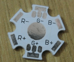
Special mounting pads are sold for such LEDs, and the pin assignments are even indicated on them.
RGBW LEDs cannot be ignored; their difference is that in their housing there is another crystal emitting white light.

Naturally, we could not do without strips with such LEDs.

This picture shows a strip with RGB LEDs, assembled according to a circuit with a common anode; the glow intensity is adjusted by controlling the “-” (minus) of the power source.
To change the color of an RGB tape, special RGB controllers are used - devices for switching the voltage supplied to the tape.
Here is the RGB SMD5050 pinout:

And the tapes, there are no special features of working with RGB tapes, everything remains the same as with single-color models.

There are also connectors for connecting LED strips without soldering.

Here is the pinout of a 5 mm RGB LED:

How the color of the glow changes
Color adjustment is carried out by adjusting the brightness of the radiation from each of the crystals. We have already looked at.
The RGB controller for tape works on the same principle; it contains a microprocessor that controls the negative terminal of the power source - connects and disconnects it from the circuit of the corresponding color. Usually a remote control is included with the controller. Controllers come in different capacities, their size depends on this, starting from such a miniature one.

Yes, such a powerful device in a case the size of a power supply.

They are connected to the tape according to the following scheme:

Since the cross-section of the tracks on the tape does not allow connecting the next section of the tape in series with it, if the length of the first exceeds 5 m, you need to connect the second section with wires directly from the RGB controller.
But you can get out of the situation and not pull additional 4 wires 5 meters from the controller and use an RGB amplifier. For it to work, you need to stretch only 2 wires (plus and minus 12V) or power another power supply from the nearest 220V source, as well as 4 “information” wires from the previous segment (R, G and B) they are needed to receive commands from the controller, so that the entire structure glows equally.

And the next segment is already connected to the amplifier, i.e. it uses the signal from the previous piece of tape. That is, you can power the tape from the amplifier, which will be located directly next to it, thereby saving money and time on laying wires from the primary RGB controller.
We adjust RGB-led with our own hands
So, there are two options for controlling RGB LEDs:
Here is a version of the circuit without using Arduino and other microcontrollers, using three CAT4101 drivers capable of delivering current up to 1A.

However, now controllers are quite cheap and if you need to regulate the LED strip, it is better to purchase a ready-made option. Circuits with Arduino are much simpler, especially since you can write a sketch with which you will either manually set the color, or the selection of colors will be automatic in accordance with a given algorithm.
Conclusion
RGB LEDs make it possible to create interesting lighting effects; they are used in interior design, as backlighting for household appliances, and for the effect of expanding the TV screen. There are no special differences when working with them from conventional LEDs.
They can shine with white light, but not everyone knows that this light is very different from the light that monochrome white strips shine with.
White LED strips use a phosphor substance - a substance that can convert the energy it absorbs into light radiation (luminesce). Therefore, the light is soft and pleasant. In RGB multicolor strips, white light is achieved by mixing red, blue and green (RGB). Since even in the highest quality tapes the power and depth of each color may vary slightly, white turns out to be off-white.
If you are still undecided whether you want white or multi-color backlighting, we would like to introduce you to the 2in1 option: RGB+W.
There are many options for RGBW LED strips on the market that combine RGB and white crystals. Specially designed controllers allow you to control all colors at once from one remote control. Adjust their brightness and hue.
Often RGB+W LED strip is produced in two rows. One row has multi-color diodes, the second one has single-color LEDs. Personally, we prefer to use two separate strips instead of one single row. This is almost always much more profitable, since it is somewhat more difficult to produce double-row tape, and only marketing distinguishes it from two parallel tapes.
The advantages of using two different strips instead of one double-row are obvious and we have already considered them (see We are against double-row LED strips)
How does RGBW lighting work?
Any RGB+W LED strip has 6 pins (4 for RGB and two for W). All 6 wires are connected to a special controller (the brain of your lighting). The controller is controlled via radio via a remote control or via a smartphone. You have the opportunity to control both white light and multi-colored light separately. You can also add blue or yellow light to the main white to get shades from cold to warm light, which is sometimes very important.
What's better to buy?
In our experience, almost any single-color monochrome tape interrupts RGB, so we recommend installing an RGB tape with a minimum power of 7.2 W/m and supplementing it with a white tape based on your wishes: if this is the main light, then >17 W/m if it is additional lighting, then ~9W/m. The minimum power RGB tape is enough to change the shade, and if you turn off the white tape and leave only the multi-color one, then even 7.2 W/m can fill your room with colorful light.
- If you have a fairly powerful white tape ~19W/m, then RGB should still be taken with SMD5050 60 diodes per meter 14.4W, otherwise there is a chance that if you turn it on at the same time, it will not be visible at all.
- It is always better to take a white ribbon in a neutral or daytime white color. By playing with shades you can always make it warmer or colder.


