Circuit diagram of an electronic clock on pic16f628a - devices based on MK - radio-bes - electronics for the home. Do-it-yourself clock on a microcontroller Electronic clock on pic16f628a with a common anode
Clock on PIC16F628A and DS18B20 temperature sensor.
4 segment LED indicator.
Animated display change.
A variant of a simple clock on the popular and affordable PIC16F628A microcontroller. In fact, the AVR project began with them.
Description of the watch.

1. Functions.
– clock, time display format 24-hour, hours:minutes.
– digital accuracy correction. Daily correction is possible ±25 sec. The set value of 1 hour 0 minutes 30 seconds will be added/subtracted from the current time.
– thermometer.
– indication. Alternately.
– customizable animation of changing readings.
– use of non-volatile memory of the microcontroller to save settings when the power is turned off.
– if in the main mode you press the buttonPLUS , then the time is displayed on the indicators if you click onMINUS - temperature. When the buttons are released, the automatic change of readings resumes.
2. Setup.
2.1. When the power is turned on, the clock is in main mode.
2.2. By pressing a buttonSET enters the settings mode and selects a parameter to install. Available for installation in turn:
– minutes;
- watch;
– seconds (reset to zero when you press the buttonsPLUS orMINUS );
– correction value. In the most significant digit the symbol "With ";
– time of indication of the current time. In the highest digits the symbols "tc ". Setting range 0÷99 sec. If set to 0, the time will not be displayed;
– temperature indication time. In the highest digits the symbols "tt ". Setting range 0÷99 sec. If set to 0, the temperature will not be displayed;
– selection of animation effect. In the highest digits the symbols "EF ". If set to 0, information changes will be carried out without effects, if automatic mode is selected (symbolA ), then the effects will change alternately. If the mode is selectedr , then the effects will change randomly.
– select animation speed. In the most significant digit the symbol "P ". The setting range is 0÷99. One unit corresponds to approximately 2 ms, the higher the value, the slower the animation.
2.3. The parameter being set flashes.
2.4. By holding the buttonsPLUS / MINUS the parameter is quickly set.
3. Notes.
It is necessary to balance the speed of animation and the time it takes to display information. If slow animation and short display time are selected, it may turn out that the information does not have time to be completely updated before the next shift.
When the main power is turned off (+12V) the indication turns off, the clock continues to run. The MK is powered from a backup source.
The archive includes firmware for indicators with a common cathode and anode, a project in Proteus and a description.
Questions, wishes in the forum.
11.03.2015
Added updated firmware for an indicator with a common cathode. The new firmware has more animation effects and minor changes in the algorithm. Detailed description in the archive.
I offer two very simple circuits for self-assembly, namely a clock on a PIC and AVR microcontroller. The basis of one circuit is the AVR Attiny2313 microcontroller, and the other is PIC16F628A
These clock circuits on a microcontroller will greatly help novice radio amateurs understand the issues of operation and programming of microcontrollers.
Let's take a closer look at this simple circuit: Power can be supplied either from three AA batteries or from

The Attiny2313 microcontroller is clocked by 16 MHz quartz. As a time counter, the internal circuit of the microcontroller uses a 16-bit timer with a divider by 256. As soon as the internal counter counts to 625, an interrupt occurs. Therefore, we will have interruptions 100 times per second.
The time interval is taken into account in global variables, and each interrupt requires the millisecond value to be increased by one. As soon as the number of milliseconds reaches 100, you need to increase the value of seconds by one, and reset the milliseconds to zero. And so on in accordance with the same algorithm up to tens of hours, which are reset only when the value reaches 24 and without increasing the next digit.
In accordance with this principle, we create the current time value recorded in global variables. Now we need to visually display this data. Since the microcontroller has a limited number of ports, we will use such a feature as the inertia of the sa15-11gwa digital segment indicator. The cathodes of its indicators are connected in parallel, and the anodes have separate control, which allows you to display a number on any of the four indicators at any time.
By quickly switching the microcontroller port to which all the cathodes are connected and quickly switching the anodes, it creates the illusion that all four numbers are showing in the segment indicator, although only one of the segments is actually working. If the current time is 11:57, then first we display number one on the first clock indicator, after 1 ms we display number 1 on the second indicator, after another 1 ms we display 5 on the 3rd indicator, after 1 ms we display 7 on the 4th indicator and so on cyclically, updating each indicator after 1 ms.
The state of the clock control buttons is polled at the end of each display cycle about 40 times per second.
Download the printed circuit board drawing made in the program and the firmware for the microcontroller from the link above. and directly about the intricacies of the firmware, read here.
This design, although based on a different type of microcontroller, is no less complex than the previous circuit.

The operating algorithm of the firmware is also simple; the archive contains very detailed comments on the program code. Two toggle switches kn1 and kn2 are designed to correct the time - hours and minutes. The accuracy of the watch depends on the frequency of the quartz used.
Structurally, the clock is made on two printed circuit boards located side by side at an angle of 90 degrees. The indicator is located on the first board, and all the other electronics are on the second. Backup power is provided by three batteries placed in a holder made from an old Chinese lighter with an LED. For power supply from an AC mains, any 5V and 150mA current is suitable.

The archive, which you can download from the green link, contains the layout of both printed circuit boards in the Sprint Layout program and the firmware for the PIC microcontroller with the source code of the program for MP_LAB IDE, with detailed comments.
And the program itself can also be found here
This design has digital correction of the accuracy of the stroke, as well as a built-in thermometer, which alternately displays temperature readings on the LED display with the exact time. The clock design uses a non-volatile microcontroller memory that saves settings and settings even when the external power is lost.

To control the anodes of LED indicators, transistor switches are used according to a standard switching circuit.

When you turn it on for the first time, an advertising screen appears on the display for one second. Then the time is displayed. Pressing the SET_TIME button switches the indicator in a circle from the main clock mode:
Absolutely, in all cells, holding down the PLUS/MINUS buttons performs accelerated installation. If the settings were changed by the user, then after 10 seconds the new values will be stored in the non-volatile memory of the microcontroller and will be read. When flashing the MK firmware, set it as follows:

You can evaluate the external design of the device from the photographs below; the stitching and additional files for the design can be downloaded from the link just above.

Shift schedules are implemented in the alarm clock firmware: 4/5 (four on the fifth) – 4 days in 1 shift, 1 day off, 4 days in 2 shifts, 1 day off, 4 days at night, 1 day off; – day, night, 2 days off; On weekdays – Mon-Fri - working days, Sat-Sun - Closed; (Holidays are not taken into account); Daily.
The user himself selects the type of alarm schedule and sets any alarm time. In the 4/5 and day, night, 2 weekend options, you must additionally select the current shift.
In addition, the following functions are implemented in the MK firmware: Transition to the summer-winter period; Time adjustment; Accelerating alarm signal; Displaying zero in the hour and date digits

The clock circuit is based on the DS1307 clock chip and the MEGA8 microcontroller. The circuit (placed in the archive with MK firmware and printed circuit board drawings) is designed for the use of seven-segment digital indicators with a common anode for a voltage of 5V. (ATTENTION! For simplicity, ballast resistors are not shown in the diagram. They need to be installed on each segment of indicators. There are 112 pieces in total. The nominal value is calculated according to the documentation. I used segment indicators like fys15011 and fyd-5622. If you use more powerful ones, then most likely without Additional transistor switches are not needed.
The printed circuit board drawing was developed for an existing box from an old broken watch. You can connect a low-power load to the Alarm connector, say a musical card, and use jumper JP1 to disconnect the internal beepper. The microcontroller can be flashed directly on the board, which greatly facilitates setup in case of modification of the design.
Setting the clock
To do this, you need to enter the parameter setting mode:
Parameter-Value-Save in memory
P.01 - CLOCK [-]
P.02 - MINUTES [-]
P.03 - DAY [-]
P.04 - MONTH [-]
P.05 - YEAR [-]
R.06 - Alarm type [+] (1-4/5; 2-5/8; 3-railway schedule; 4-daily)
P.07 - CHANGE [+]
P.08 - Bud.1.HH [+]
P.09 - Bud.1.MM [+]
P.10 - Bud.2.CHH [+]
P.11 - Bud.2.MM [+]
P.12 - Bud.3.CHH [+]
P.13 - Bud.3.MM [+]
P.14 - Adjustment (D.H) [+]
P.15 - Summer/winter period [+]
P.16 - Accelerating beeper [+]
P.17 - Display leading zero in hour digit [+]
P.18 - Display leading zero in date digit [+]
Alarm Setting: Button On/On Alarm. - On/On is carried out, in this case: With alarm type 1: Alarm 1 - 1st shift; Bud.2 - shift; Bud.3 - 3rd shift;
Shift schedule: 1,2,3,4 - first shift; 5 - day off; 6,7,8,9 - second shift; 10 - day off; 11,12,13,14 - 3rd shift; 15.16 - day off; Then the days repeat.
With the first type of alarm 2: Alarm 1 - sets the alarm time; Bud.2, Bud.3 - does not work; Shift schedule: Weekdays.
With the third type of alarm: Alarm 1 - the time of day is set; Bud.2 - sets the time at night; Bud.3 - does not work;
Shift schedule: – day, night, 2 days off;. When the alarm type is 4 Alarm 1, Alarm 2, Alarm 3, the time is set; If you plan to use only one alarm clock, set the times of three to the same time.
With shift schedule: Daily. If you press the Alarm Off buttons. in parameter setting mode, the settings will be exited without saving.
Adjustment: When making adjustments, the following method is used: +/- Ch.D, where: Ch is the number of seconds adjusted per hour (max 9). D - seconds adjusted per day. ATTENTION! No adjustments are made when the power is turned off. When you turn it on, check that the time is correct.
Schematic diagram of an electronic clock with an alarm clock on a microcontroller:

As can be seen from the clock diagram, it is the only microcircuit used in this device. A 4 MHz quartz resonator is used to set the clock frequency. To display the time, red indicators with a common anode are used; each indicator consists of two digits with decimal points. In the case of using a piezo emitter, capacitor C1 - 100 μF can be omitted.
You can use any indicators with a common anode, as long as each digit has its own anode. To ensure that the electronic watch is clearly visible in the dark and from a great distance, try to choose a larger ALS.

The clock display is dynamic. At a given time, only one digit is displayed, which allows you to significantly reduce current consumption. The anodes of each digit are controlled by a PIC16F628A microcontroller. The segments of all four digits are connected together and, through current-limiting resistors R1 ... R8, connected to the terminals of the MK port. Since the indicator lights up very quickly, the flickering of the numbers becomes unnoticeable.
Momentary buttons are used to set minutes, hours and alarm clock. Pin 10 is used as an output for the alarm signal, and a cascade of transistors VT1,2 is used as an amplifier. The sound emitter is a piezoelectric element of the ZP type. To improve the volume, you can replace it with a small speaker.
The clock is powered from a stabilized 5V source. It can also be powered by batteries. The watch has 9 display modes. Switching between modes is carried out using the “+” and “-” buttons. Before displaying the readings themselves, a short hint about the name of the mode is displayed on the indicators. The duration of the hint display is one second.

Using the "Correction" button, the alarm clock is switched to settings mode. In this case, a short-term prompt is displayed for half a second, after which the adjusted value begins to blink. Correction of readings is carried out using the “+” and “-” buttons. When you press the button for a long time, the auto-repeat mode is activated at the specified frequency. All values, except hours, minutes and seconds, are written to EEPROM and restored after power cycle.
If no button is pressed within a few seconds, the electronic clock switches to time display mode. By pressing the "On/Off" button the alarm clock turns on or off, this action is confirmed by a short sound. When the alarm clock is on, the dot in the low-order digit of the indicator lights up. I was thinking about where to put the clock in the kitchen, and decided to mount it directly into the gas stove :) The material was sent by in_sane.
Discuss the article ELECTRONIC ALARM CLOCK
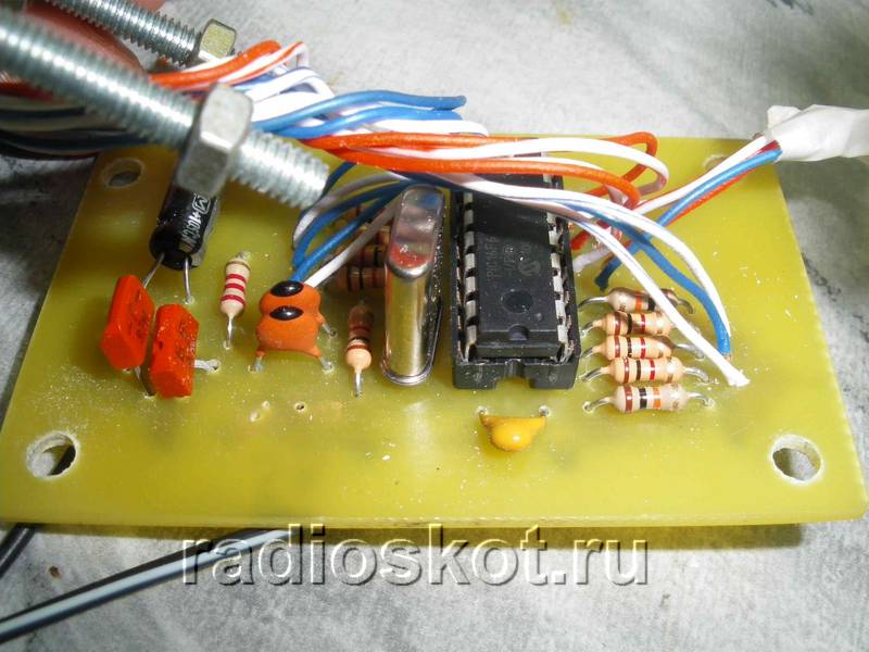
These electronic watches are the simplest. They were assembled in a few hours. The basis is a PIC16F628A microcontroller; in addition to it, the clock contains several simple and cheap elements; the information is displayed on a 4-digit (clock) LED indicator. The circuit is powered from the mains and also has a backup power supply. This design can be recommended for beginners; I specifically provided the original program with detailed comments to make it easier to understand what and how it works.
clock diagram:
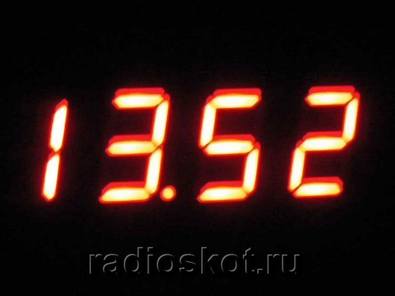
The circuit is very simple, simple and the algorithm of their work (see comments in the source). Buttons kn1 and kn2 are used to correct the time - hours and minutes, respectively. The clock has a 24 hour display format. In the 1st digit of the clock, an insignificant zero has been suppressed. The accuracy of the clock depends entirely on the frequency of the quartz resonator. But even without special selections of quartz and capacitors in the clock generator, the clock runs very accurately.
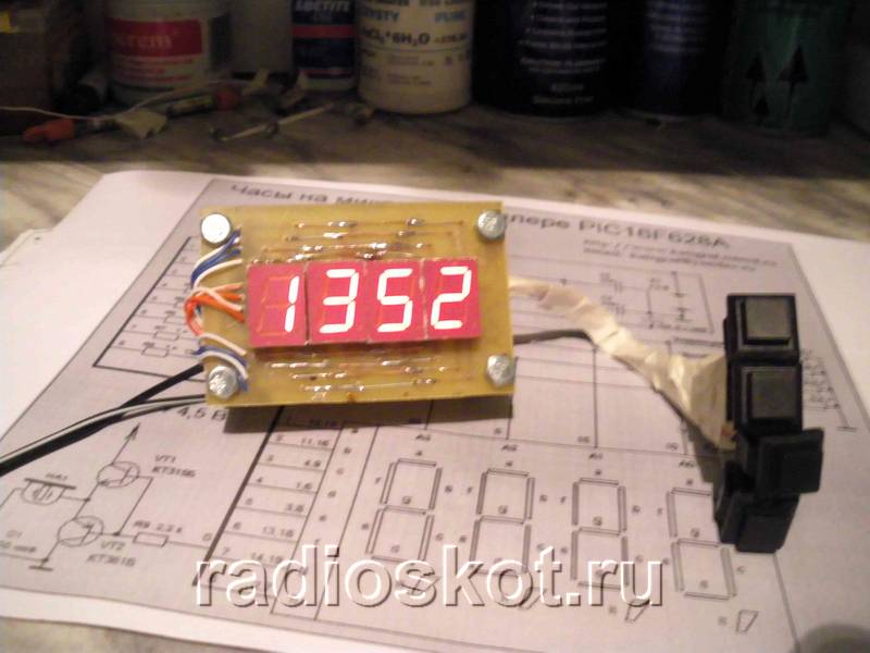
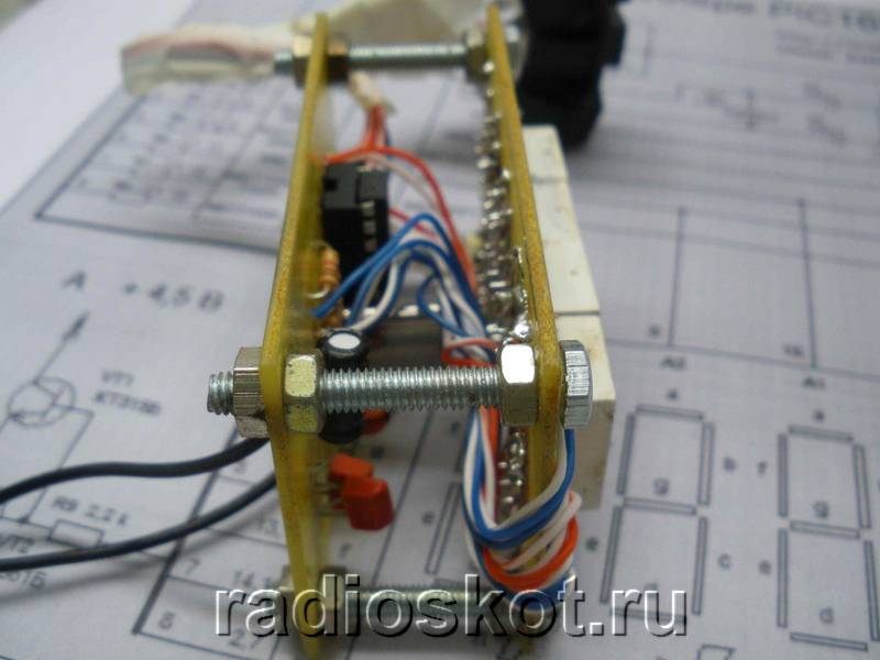
The clock is assembled on 2 printed circuit boards, docked one to the other at an angle of 90 degrees. The entire indicator is placed on one board, and everything else is on the other. The backup battery was broken from a Chinese lighter with an LED flashlight. We remove the LED and install the battery holder on the board. The photo shows that cut-off resistor leads are connected to the batteries - they hold this entire structure. Of course, the capacity of such batteries is small, but when the watch is powered from the mains, no current is consumed from the batteries. They power the circuit only if there is no mains power. In this case, only the microcontroller is powered, the indicator is not powered by batteries, so it goes out, and the clock continues to run. The control buttons are located on the board in any convenient place on the case. The design of the buttons can be any. To supply power from the network, a Chinese power supply adapter was used, to which a board with a 7805 chip (5-volt stabilizer) was added. In general, any power supply with an output voltage of 5V and a current of 150mA will do.
The program is written in such a way that it can be used for an initial study of the PIC microcontroller; the action of almost every command is commented on. If desired, you can easily add additional functions to it, such as a calendar, timer, stopwatch, etc.
Clock with a small 4-digit indicator. The dot between hours and minutes flashes at a frequency of 0.5 seconds. Can be built into any object: a desk calendar, a radio, a car. Estimated error - 0.00002%. In practice, for six months there was never a need for correction.
Power supply 4.5 - 5 volts, current up to 70mA. The voltage stabilizer is located in the adapter plug. It is assembled on a 3-watt transformer and a high-frequency converter - stabilizer according to a standard circuit. For a car, of course, a transformer is not needed. The microcircuit without a heatsink practically does not heat up. Connector for 3.5mm power supply. Quartz 4 MHz. Any low-power n-p-n transistors.
Any buttons. The length of the button pusher is selected based on the design requirements. You can also solder buttons on the conductor side. Each time you press the button, a unit is added. When held, the counting speeds up to a reasonable speed.
Resistors MLT - 0.25. R7 - R14 300 - 360 Ohm. R3 - R6 1-3 kOhm. Batteries: 4 pieces of GP-170, or similar. When the mains voltage is turned off, they only supply power to the microcontroller. They hold up for 8 days exactly, I checked. Diodes with the lowest voltage drop in the forward direction. The boards are made of one-sided foil fiberglass.
 |
 |
Before installing the microcontroller into the panel of the manufactured board, turn on the power and measure the voltage on the 14th leg of the socket. It should be 4.5 - 4.8 volts. On the 5th leg 0 volts. If you are not sure about the quality of the manufactured board or the serviceability of the parts, check the device without a microcontroller.
This is done very simply:
- Insert a jumper from the bare wire into the socket, terminals 1 and 14. This means that +4.5 volts from the first leg will open transistor VT 2 through a resistor and the cathode of the clock unit indicator will be connected to zero.
- Connect any wire with one end to +, and with the other end alternately touch terminals 6,7,8,9,10,11,12,13 of the socket.
- At the same time, observe the lighting segments and their correspondence to the diagram: + on the 6th leg - segment “g” is lit and so on.
- Move the jumper to terminals 2 and 14 of the socket. Check all segments of the minutes unit indicator.
- Jumper 18 and 14 - tens of hours are checked, 17 and 14 - tens of minutes.
If something doesn't work correctly, fix it. If everything is correct, program the microcontroller and insert it into the socket with the power off. HEX file is attached. Turn on the power and get a ready-made watch.
If you buy all the parts, including resistors, then, according to my diagram, the device will cost about 400 rubles:
- - 22.8 UAH
- - 10 UAH
- FYQ 3641AS21 - 9.3 UAH
- Panel - 3 UAH
- Quartz - 1.5 UAH
Source: www.cxem.net
| This diagram is also often viewed: |