Detailed calculation of the automatic fire extinguishing system. Mistakes in water fire extinguishing projects. An example of the calculation of a sprinkler installation of water fire extinguishing
The sprinkler system of water fire extinguishing is practical and functional. It is used in entertainment facilities, commercial and industrial buildings. The main feature of sprinkler lines is the presence of sprinklers with polymer inserts. Under the influence of high temperatures, the insert fuses, activating the fire extinguishing process.
Scheme of a sprinkler fire extinguishing system
The structure of a typical system includes the following elements.
- control modules.
- Pipeline.
- Sprinkler sprinklers.
- control module.
- Gate valves.
- impulse module.
- Compressor equipment.
- Measuring instruments.
- Pumping plant.
When calculating fire extinguishing systems, the parameters of the room (area, ceiling height, layout), requirements of industry standards, requirements of the technical assignment are taken into account.
Calculation of water sprinkler installations must be carried out by qualified specialists. They have specialized measuring instruments and the necessary software.
System Benefits
Sprinkler fire extinguishing systems have many advantages.
- Automatic activation in the event of a fire.
- Simplicity of basic working schemes.
- Maintaining performance over a long period of time.
- Serviceability.
- Acceptable cost.
System Disadvantages
The disadvantages of sprinkler systems include.
- Dependence on the regular water supply line.
- Impossibility of application on objects with a high degree of electrification.
- Difficulties when using in conditions of negative temperatures (requires the use of air-water solutions).
- Unsuitability of sprinklers for reuse.
An example of the calculation of a sprinkler installation of water fire extinguishing
The hydraulic calculation of the sprinkler fire extinguishing system allows you to determine the operating pressure indicators, the optimal pipeline diameter and line performance.
When calculating sprinkler fire extinguishing in terms of water consumption, the following formula is used:
Q=q p *S, where:
- Q is the performance of the sprinkler;
- S is the area of the target object.
Water flow is measured in liters per second.
The calculation of the performance of the sprinkler is made according to the formula:
q p = J p * F p , where
- J p - irrigation intensity established by regulatory documents, in accordance with the type of premises;
- F p is the coverage area of one sprinkler.
The fill efficiency factor is presented as a number, not accompanied by units.
When calculating the system, engineers determine the diameter of the sprinkler outlets, the consumption of materials, and the optimal technological solutions.
If you need a calculation of a sprinkler fire extinguishing system, contact the staff of "Teploognezashchita". Specialists will quickly cope with the task, provide recommendations on solving typical and non-standard issues.
Determination of operating parameters of the system.
The hydraulic calculation of the sprinkler network is aimed at determining the water flow, as well as determining the required pressure at the water feeders and the most economical pipe diameters.
According to NPB 88-2001*, the required amount of water to extinguish a fire is:
Q=q*S, l/s
Where q
– required irrigation intensity, hp/m2;
S
- area for calculating water consumption, m.
The actual consumption of the fire extinguishing agent is determined based on the technical characteristics of the selected type of sprinkler, the pressure in front of it, the conditions for arranging the required number of sprinklers to protect the calculated area, including if it is necessary to install sprinklers under process equipment, platforms or ventilation ducts, if they prevent irrigation of the protected surface. The estimated area is accepted in accordance with NPB 88-2001, depending on the group of premises.
Many designers, when determining the actual water flow rate, either take the minimum required flow rate as the design flow rate, or stop the calculation when the required amount of fire extinguishing agent is reached.
The error lies in the fact that in this way the irrigation of the entire normative calculated area with the required intensity is not ensured, since the system does not calculate and does not take into account the actual operation of the sprinklers on the calculated area. Consequently, the diameters of the main and supply pipelines are incorrectly determined, pumps and types of control units are selected.
Let's look at the above with a small example.
Premises need to be protected S=50 m2, with the required intensity q=0.08 l/s*m2
According to NPB 88-2001*, the required amount of water to extinguish a fire is: Q=50*0.08=4 l/s.
According to clause 6. App. 2 NPB 88-2001*, the estimated water flow Qd, l/s, through the sprinkler is determined by the formula:
Where k– sprinkler performance coefficient, taken according to the technical documentation for the product, k=0.47(for this option); H- free pressure in front of the sprinkler, H=10 m.
Since it is impossible to describe in detail the hydraulic calculation in the volume of one article, taking into account all the necessary factors affecting the operation of the system - linear and local losses in pipelines, system configuration (ring or dead end), in this example, we will take the water flow as the sum of the flow through the most remote sprinkler .
Qf \u003d Qd * n,
Where n- the number of sprinklers placed on the protected area
Qf=1.49*8=11.92 l/s.
We see that the actual consumption Qph significantly exceeds the required amount of water Q, therefore, for the normal operation of the system with all the required conditions, it is necessary to provide for all possible factors affecting the operation of the system.
Automatic installation of sprinkler water fire extinguishing, combined with fire hydrants.
Sprinkler sprinklers and fire hydrants are two fire-fighting systems that have the same purpose, but a different functional construction structure, so their combination causes some confusion, since you have to be guided by different regulatory documents to build a common system.
According to paragraph 4.32 of NPB 88-2001 *, "In sprinkler water-filled installations on supply pipelines with a diameter of 65 mm or more, installation of fire hydrants according to SNiP 2.04.01-85 * is allowed."
Consider one of the most common options. This example often comes across in multi-storey buildings, when, at the request of the customer and in order to save money, they combine an automatic sprinkler fire extinguishing system with an internal fire water supply system.
According to clause 9.1 of SNiP 2.04.01-85 *, with the number of fire hydrants 12 or more, the system should be taken as an annular one. Ring networks must be connected to the outer ring network with at least two inputs.

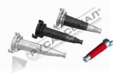
Schema errors on the image 2:
? The sections of the supply pipeline to sections with more than 12 PCs "A + B" and "G + D" are dead ends. The floor ring does not meet the requirements of clause 9.1 of SNiP 2.04.01-85*.
“Internal cold water plumbing systems should be adopted:
- dead-end, if a break in the water supply is allowed and with the number of fire hydrants up to 12;
- ring or with looped inputs with two dead-end pipelines with looped inputs with two dead-end pipelines with branches to consumers from each of them to ensure continuous water supply.
Ring networks must be connected to the outer ring network with at least two inputs.
P. 4.34. NPB 88-2001*: "A section of a sprinkler installation with 12 or more fire hydrants must have two inputs."
? According to clause 4.34. NPB 88-2001*, “for sprinkler installations with two or more sections, the second input with a valve is allowed to be made from an adjacent section.” Section "A + G" is not such an input, since after it there is a dead-end section of the pipeline.
? The requirements of clause 6.12 are violated. SNiP 2.04.01-85*: the number of jets supplied from one riser exceeds the standard values. "The number of jets supplied from each riser should be taken no more than two."
This scheme is appropriate when the number of fire hydrants in the sprinkler section is less than 12.

On figure 3 each section of a sprinkler installation with more than 12 fire hydrants has two inputs, the second input is made from an adjacent section (Section "A + B", which does not contradict the requirement of clause 4.34 of NPB 88-2001 *).
The risers are looped by horizontal jumpers, creating a single ring, therefore, clause 6.12. SNiP 2.04.02-84 * "The number of jets supplied from each riser should be taken no more than two" is not violated.
This scheme implies uninterrupted supply of water to the system according to I category of reliability.
Water supply for automatic water fire extinguishing installation.
Fire extinguishing systems, by their purpose, provide for the safety of people and the safety of property, therefore they must be constantly in working order.
If it is necessary to install booster pumps on the system, it is necessary to provide them with electricity and water supply with the condition of uninterrupted operation, i.e. according to I category of reliability.
Water fire extinguishing systems belong to category I. According to clause 4.4, the following requirements are imposed on the system:
“Category I - it is allowed to reduce the supply of water for household and drinking needs by no more than 30% of the estimated consumption and for production needs to the limit established by the emergency schedule of the enterprises; the duration of the decrease in supply should not exceed 3 days. An interruption in the water supply or a decrease in the supply below the specified limit is allowed for the time of shutting down the reserve elements of the system (equipment, fittings, structures, pipelines, etc.), but not more than 10 minutes.
One of the mistakes encountered in the projects is that the automatic water fire extinguishing system is not provided for the I category of water supply reliability.
This arises due to the fact that item 4.28. NPB 88-2001* states “Supply pipelines may be designed as dead ends for three or less control units”. Guided by this principle, designers often, when the number of control units is less than three, but the installation of fire booster pumps is required, one is provided for input to fire extinguishing systems.
This decision is not correct, since the pumping stations of automatic fire extinguishing installations should be classified as reliability category I, according to Note. 1 p. 7.1 of SNiP 2.04.02-84 "Pumping stations that supply water directly to the network of fire-fighting and combined fire-fighting water supply should be classified as category I."
According to clause 7.5 of SNiP 2.04.02-84, “The number of suction lines to the pumping station, regardless of the number and groups of installed pumps, including fire pumps, must be at least two. When turning off one line, the rest should be designed to skip the full design flow for pumping stations of categories I and II.
Based on all of the above, it is advisable to pay attention to the fact that, regardless of the number of control units of an automatic fire extinguishing installation, if there is a pumping installation on the system, it must be provided according to reliability category I.
Since at present the design documentation is not agreed by the State Fire Supervision authorities before the start of construction and installation work, the correction of errors after the installation is completed and the facility is handed over to the supervisory authorities entails unjustified costs and an increase in the time for putting the facility into operation.
S. Sinelnikov, Technos-M+ LLC
- This list contains a fairly exhaustive list of options applicable to most calculations. Let's consider the program in more detail. Interface and program operation
The interface of the program does not cause any particular complaints. All elements are quite obviously located and perform their functions. Mastering does not require time costs for any person more or less habitually working in the WINDOWS environment. The interface is built on tabs, between which you can switch at any time to make changes. In the first tab, general project data is entered, which are then used when building a report. The main working window (or windows, depending on the number) is the section window. There, in a tabular form, the initial data is entered, as well as intermediate calculations for flow rates and pressure are made.

 I will not bore you with a description of the parameter entry procedure, especially since all this is explained in detail in video tutorials that can be called up by pressing Ctrl + F1 (provided you have an Internet connection). I will only note that the input of parameters is carried out quite simply, if there is an axonometric diagram, or at least a section plan (for preliminary calculation) with dimensions applied. In addition to supply and distribution pipelines, deluge curtains, as well as fire hydrants of a combined fire-fighting water supply system, can be taken into account in the calculation. One of the disadvantages of the program is the lack of a graphical component that would allow you to visually control the input of fire extinguishing section parameters. This feature seems to me extremely useful, and the inclusion of a brief axonometry in the report would make it very descriptive. An example of such a function can only be seen in foreign software at present.
  An excellent feature included in the program is the ability to automatically enter the hydraulic parameters of equipment (sprinklers, fire hydrants and diaphragms, control units and flexible corrugated pipes) when choosing it from the built-in catalog. After the end of the calculation of the dictating section (up to the control unit), on the tab "Selection of pumps" the parameters are entered and the calculation of fire extinguishing pumping equipment is performed.
  Variants of hydraulic schemes for switching on fire pumps includes up to 5 pumps (main and standby), connected both in parallel and in series. Using the “Additional / calculations” tab, the number of branch pipes for connecting fire equipment, the volume of the tank and the minimum required diameter of the supply pipeline are automatically calculated. Report The result of the program is a report in PDF format. The section calculations included in the report can be selected. Price The cost of the HydroVPT software can be calculated based on the time of use:
- 1 month - 2,500 rubles;
- 4 months - 6,000 rubles;
- 12 months - 12,000 rubles;
- without time limit - 25,000 rubles.
- When you purchase the program with unlimited use, you get free support and updates forever.
- Software protection allows you to use it on different computers, since the key file is located on a flash drive. Thus, there is no need to purchase several copies of the program for the company. One license is bought, and a flash drive with a key is transferred between employees if necessary.
- practically the first and only program of its kind;
- availability of a certificate of conformity, which makes it possible to include program reports in the design documentation;
- clear and user-friendly interface;
- when learning how to work with the program, video tutorials are great;
- the presence of additional related calculations - the volume of the tank, the number of nozzles for fire equipment, the diameter of the suction pipeline;
- good support through the GidraVPT.rf website;
- sane price (10-20% of the cost of design work for one object).
- lack of a graphic component in the program.
Selection of automatic fire extinguishing installation
The type of automatic extinguishing installation, the method of extinguishing, the type of fire extinguishing agents, the type of equipment for fire automatics installations are determined by the design organization depending on the technological, structural and space-planning features of the buildings and premises to be protected, taking into account the requirements of Appendix A "List of buildings, structures, premises and equipment subject to protection by automatic fire extinguishing installations and automatic fire alarms” (SP 5.13130.2009).
Thus, as a designer, we install a water fire extinguishing sprinkler system in the carpentry shop. Depending on the air temperature in the warehouse of electrical goods in combustible packaging, we accept a water-filled fire extinguishing sprinkler installation, since the air temperature in the carpentry shop is more than + 5 ° С (clause 5.2.1. SP 5.13130.2009).
The fire extinguishing agent in the sprinkler water fire extinguishing installation will be water (reference book Baratov A.N.).
Hydraulic calculation of water sprinkler fire extinguishing installation
4.1 Selection of normative data for calculation and selection of sprinklers
Hydraulic calculation is carried out taking into account the operation of all sprinklers on the minimum area of the sprinkler AFS equal to at least 90 m 2 (table 5.1 (SP 5.13130.2009)).
Determine the required water flow through the dictating sprinkler:
where is the standard irrigation intensity, (table 5.2 (SP 5.13130.2009));
Sprinkler design area, .
1. Estimated water flow through the dictating sprinkler located in the dictating protected irrigated area is determined by the formula:
where K - sprinkler performance coefficient, taken according to the technical documentation for the product, ;
P - pressure in front of the sprinkler, .
As a designer, we choose a sprinkler water sprinkler model ESFR d = 20 mm.
We determine the water flow through the dictating sprinkler:
Condition check:
the condition is met.
Determine the number of sprinklers involved in the hydraulic calculation:

where - AUP consumption, ;
Consumption by 1 sprinkler, .
4.2 Placement of sprinklers in terms of the protected premises

4.3 Routing pipelines
1. The diameter of the pipeline in section L1-2 is assigned by the designer or determined by the formula:
Consumption in this area, ;
The speed of movement of water in the pipeline, .
4.4 Hydraulic network design
According to Table B.2 of Appendix B "Method of calculating the parameters of AFS for surface fire extinguishing with water and low expansion foam" (SP 5.13130.2009), we take the nominal diameter of the pipeline equal to 50 mm, for steel water and gas pipes (GOST - 3262 - 75) the specific characteristic of the pipeline is equal to .
1. Pressure loss P1-2 in section L1-2 is determined by the formula:
where is the total flow rate of the first and second sprinklers, ;
The length of the section between the 1st and 2nd sprinkler, ;
Specific characteristic of the pipeline, .
2. The pressure at sprinkler 2 is determined by the formula:
3. Sprinkler 2 consumption will be:
8. Diameter of the pipeline at the site L 2-a will be:
accept 50 mm
9. Pressure loss R 2-a Location on L 2-a will be:
10. Pressure point A will be:
11. Estimated flow in the area between 2 and point A will be equal to:
12. For the left branch of row I (figure 1, section A), flow at pressure is required. The right branch of the row is symmetrical to the left, so the flow rate for this branch will also be equal, and hence the pressure at the point A will be equal.
13. Water consumption for branch I will be:
14. Calculate the coefficient of the branch according to the formula:
15. Diameter of the pipeline at the site L a-c will be:
accept 90 mm, .
16. The generalized characteristic of branch I is determined from the expression:
17. Pressure loss R a-c Location on L a-c will be:
18. The pressure at point B will be:
19. Water consumption from branch II is determined by the formula:
20. Water consumption from branch III is determined by the formula:
accept 90 mm, .
21. Water consumption from branch IV is determined by the formula:
accept 90 mm, .
22. Calculate the row coefficient using the formula:
23. Calculate the flow rate using the formula:
24. Condition check:
the condition is met.
25. The required pressure of the fire pump is determined by the formula:
where is the required fire pump pressure, ;
Losses of pressure on horizontal sections of the pipeline,;
Pressure loss in the horizontal section of the pipeline s - st, ;
Pressure loss in the vertical section of the pipeline DB, ;
Pressure losses in local resistances (shaped parts B And D), ;
Local resistances in the control unit (alarm valve, valves, gates), ;
Pressure at the dictating sprinkler, ;
Piezometric pressure (geometric height of the dictating sprinkler above the axis of the fire pump), ;
Fire pump inlet pressure, ;
Required pressure.
26. Pressure loss in a horizontal section of the pipeline s - st will be:
27. Pressure loss in a horizontal section of the pipeline AB will be:
where is the distance to the fire fighting pumping station, ;
28. The pressure loss in the horizontal section of the BD pipeline will be:
29. Pressure loss in the horizontal sections of the pipeline will be:
30. Local resistance in the control unit will be:
31. Local resistance in the control unit (alarm valve, valves, gates) is determined by the formula:
where - pressure loss coefficient, respectively, in the sprinkler control unit, (taken individually according to the technical documentation for the control unit as a whole);
Water flow through the control unit, .
32. Local resistance in the control node will be:
We select an air sprinkler control unit - UU-S100 / 1.2Vz-VF.O4-01 TU4892-080-00226827-2006 * with a head loss coefficient of 0.004.
33. The required fire pump pressure will be:
34. The required pressure of the fire pump will be:
35. Condition check:
the condition is not met, i.e. an additional reservoir is required.
36. According to the data obtained, we select a pump for AUPT - a centrifugal pump 1D, series 1D250-125, with an electric motor power of 152 kW.
37. Determine the amount of water in the tank:
where Q us - pump flow, l / s;
Q water supply network - consumption of the water supply network, l / s;
Calculation of an automatic water feeder
Minimum pressure in the automatic water feeder:
H av \u003d H 1 + Z + 15
where H 1 is the pressure at the dictating sprinkler, m.v.s.;
Z-geometric height from the axis of the pump, to the level of sprinklers, m;
Z \u003d 6m (room height) + 2 m (pump room floor level below) \u003d 8m;
15-reserve for the operation of the installation before turning on the backup pump.
H av \u003d 25 + 8 + 15 \u003d 48 m.w.s.
To maintain the pressure of the automatic water feeder, we select the CR 5-10 jockey pump with a head of 49.8 m.w.s.
Ministry of Education and Science of the Russian Federation
Ufa State Aviation Technical University
Department of "Fire Safety"
Settlement and graphic work
Topic: Calculation of automatic water fire extinguishing installation
Supervisor:
department assistant
"Fire safety" Gardanova E.V.
Executor
student group PB-205 cc
Gafurova R.D.
Gradebook No. 210149
Ufa, 2012
Exercise
In this paper, it is necessary to perform an axonometric diagram of an automatic water fire extinguishing system indicating on it the dimensions and diameters of pipe sections, the locations of sprinklers and the necessary equipment.
Conduct a hydraulic calculation for the selected pipeline diameters. Determine the estimated flow rate of the automatic water fire extinguishing installation.
Calculate the pressure that the pumping station should provide and select equipment for the pumping station.
installation fire extinguishing pipeline pressure
annotation
The RGR on the course "Industrial and fire automatics" is aimed at solving specific problems in the installation and maintenance of fire automatics installations.
This paper shows the ways of applying theoretical knowledge to solve engineering problems on the creation of fire protection systems for buildings.
During the work:
studied the technical and regulatory documentation governing the design, installation and operation of fire extinguishing installations;
the technique of technological calculations is given to ensure the required parameters of the fire extinguishing installation;
the rules for the application of technical literature and regulatory documents on the creation of fire protection systems are shown.
The implementation of the RGR contributes to the development of students' skills of independent work and the formation of a creative approach to solving engineering problems on the creation of fire protection systems for buildings.
annotation
Introduction
Initial data
Calculation formulas
Basic principles of operation of a fire extinguishing installation
1 The principle of operation of the pumping station
2 The principle of operation of the sprinkler installation
Designing a water fire extinguishing installation. Hydraulic calculation
Equipment selection
Conclusion
Bibliography
Introduction
The most widespread at present are automatic water fire extinguishing systems. They are used on large areas to protect shopping and multifunctional centers, office buildings, sports complexes, hotels, enterprises, garages and parking lots, banks, energy facilities, military and special purpose facilities, warehouses, residential buildings and cottages.
In my version of the task, an object for the production of alcohols, ethers with utility rooms is presented, which, in accordance with paragraph 20 of Table A.1 of Appendix A of the Code of Rules 5.13130.2009, regardless of the area, must have an automatic fire extinguishing system. It is not necessary to equip the remaining utility rooms of the facility in accordance with the requirements of this table with an automatic fire extinguishing system. The walls and ceilings are reinforced concrete.
The main types of fire load are alcohols and ethers. In accordance with the table, we decide that it is possible to use a foaming agent solution for extinguishing.
The main fire load in an object with a room height of 4 meters comes from the repair zone, which, in accordance with the table of Appendix B of the set of rules 5.13130.2009, belongs to the 4.2 group of rooms in terms of the degree of fire development risk, depending on their functional purpose and fire load of combustible materials.
There are no premises of categories A and B at the facility for explosion and fire hazard in accordance with SP 5.13130.2009 and explosive zones in accordance with the PUE.
To extinguish possible fires in the facility, taking into account the available combustible load, it is possible to use a foam concentrate solution.
To equip the facility for the production of alcohols, ethers, we will choose an automatic foam fire extinguishing installation of a sprinkler type filled with a foaming agent solution. Foaming agents are concentrated aqueous solutions of surfactants (surfactants) intended to obtain special solutions of wetting agents or foam. The use of such foaming agents during fire extinguishing can significantly reduce the intensity of combustion after 1.5-2 minutes. The methods of influencing the source of ignition depend on the type of foam concentrate used in the fire extinguisher, but the basic principles of action are the same for everyone:
due to the fact that the foam has a mass much less than the mass of any flammable liquid, it covers the surface of the fuel, thereby suppressing the fire;
the use of water, which is part of the foaming agent, allows, within a few seconds, to reduce the temperature of the fuel to the level at which combustion becomes impossible;
The foam effectively prevents the further spread of hot vapors resulting from a fire, making re-ignition nearly impossible.
Due to these features, foam concentrates are actively used for fire extinguishing in the petrochemical and chemical industries, where there is a high risk of ignition of combustible and flammable liquids. These substances do not pose a threat to human health or life, and their traces are easily removed from the premises.
1. Initial data
Hydraulic calculation is performed in accordance with the requirements of SP 5.13130.2009 “Fire extinguishing and alarm installations. Design norms and rules” according to the methodology set out in Appendix B.
The protected object is the volume of the room 30x48x4m, in terms of a rectangle. The total area of the object is 1440 m2.
We find the initial data for the production of alcohols, ethers in accordance with a certain group of premises from table 5.1 of this set of rules in the section “Water and foam fire extinguishing installations”:
irrigation intensity - 0.17 l / (s * m2);
area for calculating water consumption - 180 m2;
the minimum water consumption of the fire extinguishing installation is 65 l / s;
maximum distance between sprinklers - 3 m;
the selected maximum area controlled by one sprinkler is 12m2.
duration of work - 60 min.
To protect the warehouse, we choose the sprinkler SPO0-RUo (d) 0.74-R1 / 2 / P57 (68.79.93.141.182). V3-"SPU-15" software "SPETSAVTOMATIKA" with a performance factor k = 0.74 (according to those .documentation for the sprinkler).
2. Calculation formulas
Estimated water flow through the dictating sprinkler located in the dictating protected irrigated area is determined by the formula
where q1 - FTA flow through the dictating sprinkler, l / s; - sprinkler performance coefficient, taken according to the technical documentation for the product, l / (s MPa0.5);
P - pressure in front of the sprinkler, MPa.
The flow rate of the first dictating sprinkler is the calculated value of Q1-2 in the section L1-2 between the first and second sprinklers
The diameter of the pipeline in section L1-2 is assigned by the designer or determined by the formula
where d1-2 is the diameter between the first and second pipeline sprinklers, mm;
μ - flow coefficient; - water velocity, m/s (should not exceed 10 m/s).
The diameter is increased to the nearest nominal value in accordance with GOST 28338.
The pressure loss P1-2 in the section L1-2 is determined by the formula
where Q1-2 is the total flow rate of the first and second sprinklers, l/s; t is the specific characteristic of the pipeline, l6/s2;
A - specific resistance of the pipeline, depending on the diameter and roughness of the walls, c2 / l6.
The specific resistance and specific hydraulic characteristic of pipelines for pipes (made of carbonaceous materials) of various diameters are given in Table B.1<#"606542.files/image005.gif">
The hydraulic characteristic of the rows, made structurally the same, is determined by the generalized characteristic of the calculated section of the pipeline.
The generalized characteristic of row I is determined from the expression
The pressure loss in the section a-b for symmetrical and asymmetric circuits is found by the formula.
The pressure at point b will be
Рb=Pa+Pa-b.
Water consumption from row II is determined by the formula
The calculation of all subsequent rows until the calculated (actual) water flow and the corresponding pressure are obtained is carried out similarly to the calculation of row II.
We will calculate the symmetrical and asymmetric ring schemes similarly to the dead-end network, but at 50% of the calculated water flow for each half-ring.
3. Basic principles of operation of the fire extinguishing installation
The automatic fire extinguishing installation consists of the following main elements: an automatic fire extinguishing pumping station with a system of inlet (suction) and supply (pressure) pipelines; - control units with a system of supply and distribution pipelines with sprinklers installed on them.
1 The principle of operation of the pumping station
In the standby mode of operation, the supply and distribution pipelines of sprinkler installations are constantly filled with water and are under pressure, ensuring constant readiness for extinguishing a fire. The jockey pump turns on when the pressure alarm goes off.
In the event of a fire, when the pressure on the jockey pump (in the supply line) drops, when the pressure alarm is triggered, the working fire pump is turned on, providing full flow. At the same time, when the fire pump is turned on, a fire alarm signal is sent to the fire safety system of the facility.
If the electric motor of the working fire pump does not turn on or the pump does not provide the design pressure, then after 10 s the electric motor of the standby fire pump is turned on. The impulse to turn on the standby pump is given from a pressure switch installed on the pressure pipe of the working pump.
When the working fire pump is turned on, the jockey pump is automatically turned off. After the fire source is eliminated, the water supply to the system is stopped manually, for which the fire pumps are turned off and the valve in front of the control unit is closed.
3.2 The principle of operation of the sprinkler installation
If a fire occurs in the room protected by the sprinkler section and the air temperature rises above 68 °C, the thermal lock (glass bulb) of the sprinkler is destroyed. from the sprinkler sprinkler enters the room, the pressure in the network drops.When the pressure drops by 0.1 MPa, the pressure alarms installed on the pressure pipeline are triggered, and an impulse is given to turn on the working pump.
The pump takes water from the city water supply network, bypassing the water metering unit, and delivers it to the piping system of the fire extinguishing installation. In this case, the jockey pump is automatically switched off. In the event of a fire on one of the floors, liquid flow detectors duplicate the signals about the operation of the water fire extinguishing installation (thereby identifying the place of fire) and at the same time turn off the power supply system of the corresponding floor.
Simultaneously with the automatic switching on of the fire extinguishing installation, signals about a fire, turning on the pumps and starting the operation of the installation in the corresponding direction are transmitted to the fire station room with round-the-clock stay of operational personnel. In this case, the light alarm is accompanied by sound.
4. Designing a water fire extinguishing installation. Hydraulic calculation
Hydraulic calculation is performed for the most remote and highly located ("dictating") sprinkler from the condition of operation of all sprinklers, the most remote from the water feeder and mounted on the calculated area.
We plan the route of the pipeline network and the plan for the placement of sprinklers and select the dictated protected irrigated area on the hydraulic plan-scheme of the AFS, on which the dictated sprinkler is located and carry out the hydraulic calculation of the AFS.
Determination of the estimated water flow in the protected area.
Determination of the flow rate and pressure in front of the "dictating sprinkler" (flow rate at point 1 in the diagram in Appendix 1) is determined by the formula:
=k √ H
The flow rate of the "dictating" sprinkler must provide the normative intensity of irrigation, therefore:
min = I*S=0.17 * 12 = 2.04 l/s, so Q1 ≥ 2.04 l/s
Note. When calculating, it is necessary to take into account the number of sprinklers protecting the calculated area. On the estimated area of 180 m2 there are 4 rows of 5 and 4 sprinklers, the total flow must be at least 60 l / s (see Table 5.2 of SP 5.13130.2009 for 4.2 group of premises). Thus, when calculating the pressure in front of the "dictating" sprinkler, it is necessary to take into account that in order to ensure the minimum required flow rate of the fire extinguishing installation, the flow rate (and hence the pressure) of each sprinkler will have to be increased. That is, in our case, if the flow rate from the sprinkler is taken equal to 2.04 l / s, then the total flow rate of 18 sprinklers will be approximately equal to 2.04 * 18 = 37 l / s, and taking into account the different pressure in front of the sprinklers, it will be slightly more, but this value does not correspond to the required flow rate of 65 l/s. Thus, it is necessary to select the pressure in front of the sprinkler in such a way that the total flow rate of 18 sprinklers located on the calculated area is more than 65 l/s. For this: 65/18=3.611, i.e. flow rate of the dictating sprinkler must be more than 3.6 l/s. Having carried out several variants of calculations in the draft, we determine the required pressure in front of the "dictating" sprinkler. In our case, H=24 m.w.s.=0.024 MPa.
(1) =k √ H= 0.74√24= 3.625 l/s;
We calculate the diameter of the pipeline in a row according to the following formula:
![]()
From where we get at a water flow rate of 5 m / s, the value d \u003d 40 mm and take the value of 50 mm for the reserve.
Head loss in section 1-2: dH(1-2)= Q(1) *Q(1) *l(1-2) / Km= 3.625*3.625*6/110=0.717 m.w.s.= 0.007MPa;
To determine the flow rate from the 2nd sprinkler, we calculate the pressure in front of the 2nd sprinkler:
H(2)=H(1)+dH(1-2)=24+0.717=24.717 m.w.s.
Flow rate from the 2nd sprinkler: Q(2) =k √ H= 0.74√24.717= 3.679 l/s;
Head loss in section 2-3: dH(2-3)= (Q(1) + Q(2))*(Q(1) + Q(2))*l(2-3) / Km= 7.304* 7.304 * 1.5 / 110 \u003d 0.727 m. With;
Head at point 3: H(3)=H(2)+ dH(2-3)= 24.717+0.727=25.444 m.w.s;
The total consumption of the right branch of the first row is equal to Q1 + Q2 = 7.304 l/s.
Since the right and left branches of the first row are structurally identical (2 sprinklers each), the consumption of the left branch will also be 7.304 l/s. The total flow rate of the first row is equal to Q I =14.608 l/s.
The flow rate in point 3 is divided in half, since the supply pipeline is made as a dead end. Therefore, when calculating the pressure loss in section 4-5, the flow rate of the first row will be taken into account. Q(3-4) = 14.608 l/s.
The value d=150 mm will be taken for the main pipeline.
Head loss in section 3-4:
(3-4) \u003d Q (3) * Q (3) * l (3-4) / Km \u003d 14.608 * 14.608 * 3 / 36920 \u003d 0.017 m. With;
Head at point 4: H(4)=H(3)+ dH(3-4)= 25.444+0.017=25.461 m. With;
To determine the consumption of the 2nd row, it is necessary to determine the coefficient B:
That is, B= Q(3)*Q(3)/H(3)=8.39
Thus, the consumption of the 2nd row is equal to:
II= √8, 39*24.918= 14.616 l/s;
Total flow from 2 rows: QI + QII = 14.608 + 14.616 = 29.224 l / s;
Similarly, I find (4-5)=Q(4)*Q(4)*l(4-5)/Km= 29.224 *29.224*3/36920=0.069 m.v. With;
Head at point 5: H(5)=H(4)+ dH(4-5)= 25.461+0.069=25.53 m. With;
Since the next 2 rows are asymmetrical, we find the consumption of the 3rd row as follows:
That is, B= Q(1)*Q(1)/H(4)= 3.625*3.625/25.461=0.516lev= √0.516 * 25.53= 3.629 l/s; (5)= 14.616 +3.629 = 18.245 l /s= Q(5)*Q(5)/H(5)=13.04III= √13.04 * 25.53= 18.24 l/s;
Total consumption of 3 rows: Q (3 rows) = 47.464 l / s;
Head loss in the section 5-6: (5-6) \u003d Q (6) * Q (6) * l (5-6) / Km \u003d 47.464 * 47.464 * 3 / 36920 \u003d 0.183 m. With;
Head at point 6: H(6)=H(5)+ dH(5-6)= 25.53+0.183=25.713 m. With;
IV= √13.04 * 25.713= 18.311 l/s;
Total flow from 4 rows: Q(4 rows) = 65.775 l/s;
Thus, the calculated flow rate is 65.775 l/s, which complies with the requirements of regulatory documents >65 l/s.
The required pressure at the beginning of the installation (near the fire pump) is calculated from the following components:
pressure in front of the "dictating" sprinkler;
pressure loss in the distribution pipeline;
pressure loss in the supply pipeline;
pressure loss in the control unit;
the difference between the marks of the pump and the "dictating" sprinkler.
Head loss in the control unit:
![]() .water.st,
.water.st,
The required pressure, which the pumping unit must provide, is determined by the formula:
tr \u003d 24 + 4 + 8.45 + (9.622) * 0.2 + 9.622 \u003d 47.99 m.w.s. \u003d 0.48 MPa
Total water consumption for sprinkler fire extinguishing: (4 rows) = 65.775 l / s = 236.79 m3 / h
Required pressure:
tr \u003d 48 m.w.s. \u003d 0.48 MPa
5. Equipment selection
The calculations were carried out taking into account the selected sprinkler SPOO-RUoO,74-R1/2/R57.VZ-"SPU-15"-bronze with an outlet diameter of 15 mm.
Taking into account the specifics of the facility (a unique multifunctional building with a massive stay of people), a complex system of pipelines of the internal fire-fighting water supply, the pumping unit is selected with a supply of pressure.
The extinguishing time is 60 minutes, that is, 234,000 liters of water must be supplied.
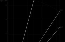
The design solution selects the pump Irtysh-TSMK 150/400-55/4 with a speed of 1500 rpm, which has a margin both in H=48 m.w.s. and in Q. of the pump=65m.
The operating characteristics of the pump are shown in the figure.

Conclusion
This RGR presents the results of the studied methods for designing automatic fire extinguishing installations, and the calculations necessary for designing an automatic fire extinguishing installation.
According to the results of the hydraulic calculation, the placement of sprinklers was determined in order to achieve a water flow rate for fire extinguishing in the protected area - 65 l/s. To ensure the normative intensity of irrigation, a pressure of 48 m.a.c. is required.
Equipment for installations is selected based on the normative minimum value of irrigation intensity, calculated flow rates and required pressure.
Bibliography
1 SP 5.13130.2009. Fire alarm and fire extinguishing installations are automatic. Design norms and rules.
Federal Law No. 123 - FZ "Technical Regulations on Fire Safety Requirements" dated July 22, 2008
Design of water and foam automatic fire extinguishing installations / L.M. Meshman, S.G. Tsarichenko, V.A. Bylinkin, V.V. Aleshin, R.Yu. Gubin; under general ed. N.P. Kopylov. - M: VNIIPO EMERCOM of the Russian Federation, 2002.-413 p.
Internet sites of manufacturers of fire fighting equipment