Homemade antenna for digital. DIY home TV antenna. Materials and calculations

The era of digital signals has arrived. All broadcast television companies began to work in a new format. Analog TVs are reaching their end. They are still in working order and are found in almost every family.
In order for older models to successfully complete their service life, and for people to be able to use them when watching digital broadcasting, it is enough to connect the DVB-T set-top box to the TV receiver and pick up the TV wave signals with a special antenna.
Any home craftsman can not buy an antenna in a store, but make it with his own hands from available materials for watching digital TV programs at home or in the country. The two most accessible designs are described in this article.
A little theory
Operating principle of an antenna for digital packet television
Any television signal propagates in space from the emitters of the transmitting television tower to the TV antenna by an electromagnetic wave of a sinusoidal shape with a high frequency, measured in megahertz.

When an electromagnetic wave passes through the surface of the receiving beams of the antenna, a voltage V is induced in it. Each half-wave of a sinusoid forms a potential difference with its own sign.
Under the influence of an induced voltage applied to a closed receiving circuit of the input signal with resistance R, an electric current flows in the latter. It is amplified and processed by the digital TV circuit and output to the screen and speakers as image and sound.

For analog models of TV receivers, an intermediate link works between the antenna and the TV - a DVB-T set-top box, which decodes digital information of an electromagnetic wave into a normal form.
Vertical and horizontal polarization of digital TV signal
In television broadcasting, state standards require electromagnetic waves to be emitted in only two planes:
- horizontal.

In this way, transmitters send emitting signals.
And users simply need to rotate the receiving antenna in the desired plane to maximize the power potential.
Requirements for a digital packet television antenna
TV transmitters propagate their signal waves over short distances, limited by the line of sight from the top point of the TV tower emitter. Their range rarely exceeds 60 km.
For such distances, it is enough to provide a small power of the emitted TV signal. But, the strength of the electromagnetic wave at the end of the coverage area should form a normal voltage level at the receiving end.
A small potential difference, measured in fractions of a volt, is induced at the antenna. It creates currents with small amplitudes. This imposes high technical requirements on the installation and quality of manufacturing of all parts of digital reception devices.
The antenna design should be:
- manufactured carefully, with a good degree of accuracy, eliminating loss of electrical signal power;
- directed strictly along the axis of the electromagnetic wave coming from the transmitting center;
- oriented according to the type of polarization;
- protected from extraneous interference signals of the same frequency coming from any sources: generators, radio transmitters, electric motors and other similar devices.
How to find out the initial data for calculating an antenna
The main parameter influencing the quality of the received digital signal, as can be seen from the explanatory first figure, is the length of the electromagnetic wave of radiation. Under it, symmetrical arms of vibrators of various shapes are created, and the overall dimensions of the antenna are determined.
The wavelength λ in centimeters can be easily calculated using a simplified formula: λ=300/F. It is enough just to find the frequency of the received signal F in megahertz.
To do this, we will use a Google search and ask it for a list of regional TV communication points for our area.
As an example, a fragment of a data table for the Vitebsk region is shown with the transmitting center in Ushachi highlighted in red.

Its wave frequency is 626 megahertz, and its polarization type is horizontal. This data is quite sufficient.
We carry out the calculation: 300/626=0.48 m. This is the length of the electromagnetic wave for the antenna being created.
We divide it in half and get 24 cm - the desired half-wave length.
The tension reaches its maximum value in the middle of this section - 12 cm. It is also called amplitude. The whip antenna is made to this size. It is usually expressed by the formula λ/4, where λ is the electromagnetic wavelength.
The simplest TV antenna for digital television
It will require a piece of coaxial cable with a characteristic impedance of 75 Ohms and a plug for connecting the antenna. I managed to find a ready-made two-meter piece in the old stock.

I cut off the outer shell from the free end with a regular knife. I take the length with a small margin: when setting up it is always easier to bite off a small piece.

Then I remove the shielding layer from this section of the cable.


The work is done. All that remains is to insert the plug socket into the connector on the TV signal set-top box and direct the bare wire of the inner core across the incoming electromagnetic wave, taking into account horizontal polarization.

The antenna should be placed directly on the window sill or secured to the glass, for example, with a piece of tape, or tied to the blind mount. Reflected signals and interference can be shielded with a strip of foil located a short distance from the central core.
Such a design can be done in literally ten minutes and does not require any special material costs. It's worth trying. But, it is capable of working in an area of reliable signal reception. My building is screened by a mountain and a multi-story building. The transmitting television tower is located at a distance of 25 km. Under these conditions, the digital electromagnetic wave is reflected many times and is poorly received. I had to look for another technical solution.
And for you on the topic of this design, I suggest you watch the video by the owner of Edokoff “How to make an antenna for digital TV”
Kharchenko antenna at 626 MHz
To receive analogue television signals of various wave frequencies, the design of a zigzag broadband antenna, which does not require complex manufacturing, worked well for me before.
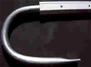
I immediately remembered one of their effective varieties - the Kharchenko antenna. I decided to use its design for digital reception. I made the vibrators from a flat copper bar, but it’s quite possible to get by with round wire. This will make it easier to bend and straighten the ends.

How to determine the dimensions of a specific antenna
Online calculator
Let's use the all-knowing Google search. We write on the command line: “Calculation of the Kharchenko antenna” and press Enter.

We choose any site you like and perform online calculations. I went into the first one that opened. This is what he calculated for me.

I presented all his data with a picture indicating the size of the Kharchenko antenna.

Manufacturing of antenna design parts
I took the information provided as a basis, but did not accurately maintain all the dimensions. I know from previous practice that the antenna works well in the broadband wavelength range. Therefore, the dimensions of the parts were simply slightly increased. The half-wave of each harmonic of the sine wave of the electromagnetic TV signal will fit into the arm of each vibrator and will be received by it.
Based on the selected data, I made blanks for the antenna.

Vibrator design features
The connection of the ends of the figure eight busbar is created in the center at the bending stage. I soldered them with a soldering iron.

I created it according to the “Moment” principle, made it with my own hands from old transformers, and has been working for two decades. I even soldered 2.5 square copper wire with it in thirty-degree frost. Works with transistors and microcircuits without burning them out.
In the near future I plan to describe its design in a separate article on the website for those who also want to make it themselves. Follow publications, subscribe to notifications.
Connecting the antenna cable to the vibrator
I simply soldered the copper core and braid to the metal of the figure eight from different sides in its center.

The cable was tied to a copper bar, bent into a loop in the shape of a semi-square vibrator. This method matches the resistance of the cable and antenna.
Screening grid design
In fact, the Kharchenko antenna often works normally without signal shielding, but I decided to show its manufacture. For the base I took a wooden block. I did not paint or varnish: the structure will be used indoors.
In the back side of the block I drilled holes for attaching the screen wires and inserted them, and then wedged them.

The result was a screen for the Kharchenko antenna. In principle, it can be made of a different design: cut from a piece of frontal armor of a tank or cut from food foil - it will work approximately the same.

On the back side of the bar I secured the vibrator structure with a cable.

The antenna is ready. All that remains is to install it on a window to work in vertical polarization.

When a television receiver is located at a great distance from the transmitting generator, the power of its signal gradually weakens. It can be increased by special electronic devices - amplifiers.
You just need to clearly see the difference between the signals received by the antenna, which can be:
- simply weakened;
- contain high-frequency interference that distorts the shape of the digital sinusoid into the shape of some kind of “doodleball”.
In both cases, the amplifier will fulfill its role and increase the power. Moreover, the TV will clearly perceive and display a weakened signal, but with an amplified signal, playback problems will arise.
The waves are designed to eliminate such interference:
- high-pressure filters;
- screens.
They must be measured with an oscilloscope, and the methods of using various designs must be analyzed individually in each specific case. The antenna is not to blame here.
Despite the huge number of television antennas presented on the consumer market, which can be easily purchased at any electronics store, interest in how to make an antenna for a TV with your own hands does not disappear. This interest can be explained by a reluctance to spend money on buying an antenna, being away from retail outlets (if you are in the outback or at the dacha) or the failure of the purchased one.
Antennas for a television receiver can be divided into several types.
- All-wave antenna– the design is easy to manufacture; it can be made from simple available materials. It picks up a digital signal quite well outside the city, where there is not much interference. When located near a broadcast tower, it can receive analog television.
- Log-periodic band antenna also easy to make. It has perfect consistency with the feeder across all ranges, without changing its parameters. Since this design has average technical parameters, it can be used in the country, or as an indoor antenna in the city.
- UHF antenna. A simplified modification of the Z-antenna is often used; it works well, regardless of the signal reception conditions.
All-wave antenna
All-wave TV signal catchers are also called frequency independent (FIN). Their designs can be different.
Of two petals
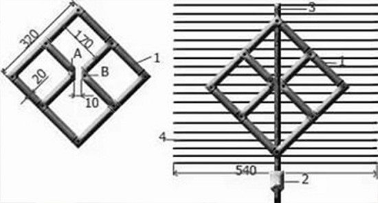
The figure shows an all-wave antenna made from two metal plates triangular in shape and two wooden slats on which copper wire is stretched in the shape of a fan.
Copper wire can be taken of any diameter, it does not play a special role. The ends of the wire are attached at a distance of 20 to 30 mm from each other. The plates with the other ends of the wire soldered together should be located at a distance of 10 mm from each other.
The metal plate can be replaced with a square piece of fiberglass, which has copper foil on one side.
Since the design of the homemade antenna is square in shape, its height will be equal to its width, and the angle between the panels will be 90 degrees. Zero potential point marked in yellow in the figure. There is no need to solder the cable braid in this place - tying it tightly will be enough.
A television signal receiver assembled in this way in the form of two lobes is capable of receiving both all decimeter channels and meter ones. Moreover, it picks up signals well in all directions. But if you install the CNA in an area of poor signal reception from a TV tower, it will only work normally with amplifier. Others can also be used.
Butterfly shaped
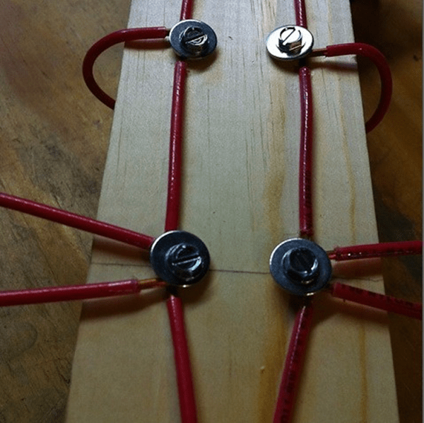
You can make a television antenna in the shape of a butterfly with your own hands. To make this fairly powerful antenna yourself, you need to prepare a board or plywood with dimensions of 550 x 70 x 5 mm, a wire with a copper core with a cross-section of 4 mm, and, accordingly, a PK75 cable.
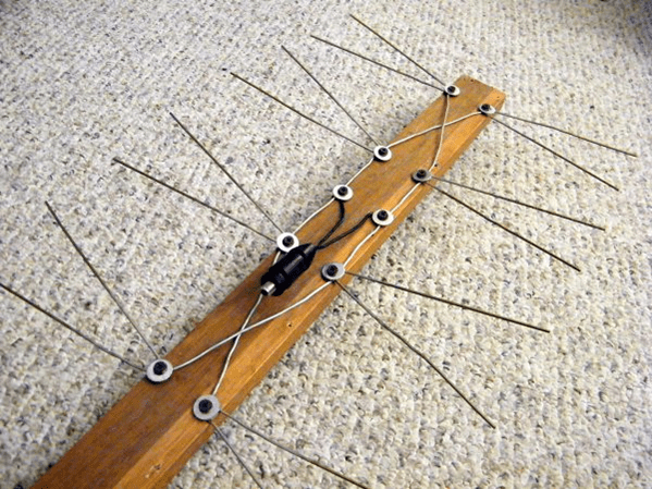
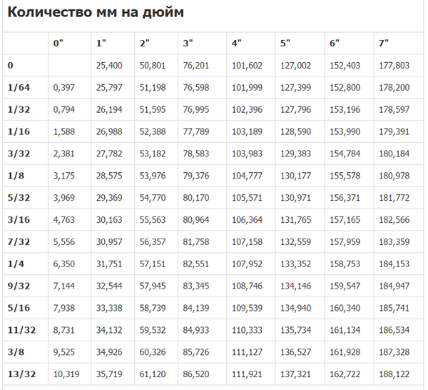
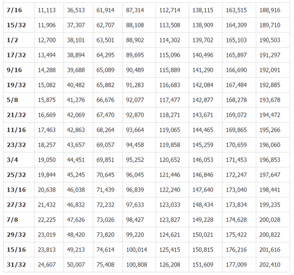
- Mark the holes on the plywood and drill them. Dimensions in the picture are in inches. Below the figure is a table for converting inches to mm.

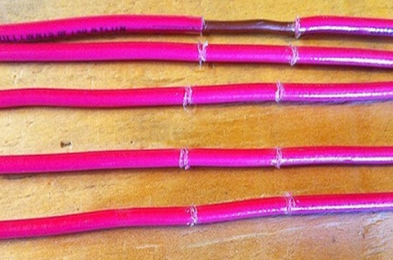
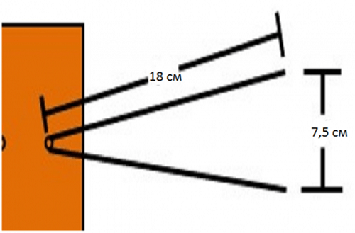
- From copper wire you need to cut 8 pieces of the same length, 37.5 cm each.
- In the center of each wire, clear sections of insulation (2 cm each), as in the figure.
- After this, you should cut off 2 more pieces of wire, already 22 centimeters each, divide them into 3 equal parts and remove the insulation at the separation points.
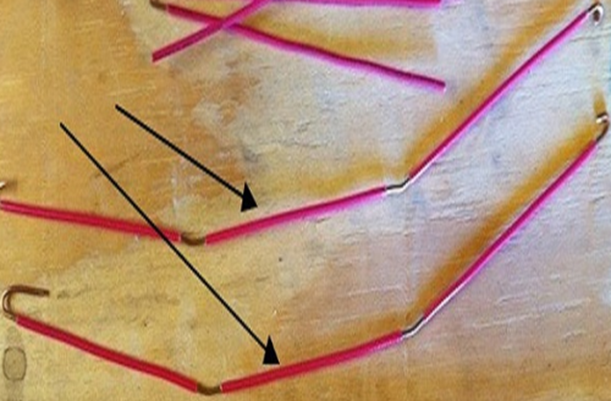
- Give the segments V-shape. You should be careful to maintain a distance of 7.5 cm between the ends of the wire. This is the optimal distance to receive a clear signal.
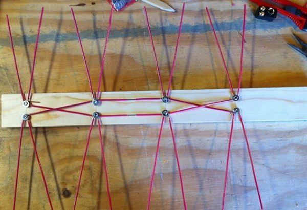
- Connect all the elements according to the figure below.
- Next, you need to purchase a socket to connect the plug to it.
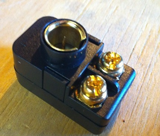
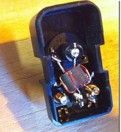
- The cable must be soldered to the coil contacts, as in the figure.

- Make 2 more pieces of wire of the required length to connect the antennae to the socket.
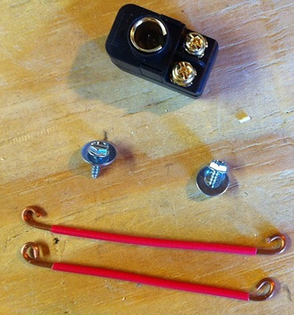
- Screw the socket onto the board and connect all the elements.

That's all - you have made an antenna for your TV with your own hands.
From beer cans
To make such an original ChNA you will need 2 cans (0.5 l or 0.75) of beer or other drink. But before you make a television antenna, you need to consider some material requirements. Namely, it is recommended to purchase a high-quality television cable with a resistance of 75 ohms per meter. Which is correct? Make sure that the central core is strong and that the braid is double and continuous.
Don’t forget, the longer the cable, the stronger the signal attenuation will be, which is especially important for receiving meter waves, in contrast to UHF, for which the length of the wire also matters, but not so much.
It will also be necessary to prepare the usual wooden trempel, a couple of self-tapping screws, electrical tape or tape and, if possible, a soldering iron with tin.
An antenna made from beer cans can receive both the UHF and meter wavelengths.
To illustrate the entire process, you can watch the video.
Log-periodic antenna
A log-periodic antenna (LPA) can be used to receive radio waves in both the meter and decimeter ranges. To make such a signal receiver, you can use an aluminum tube with a diameter of 10 mm and metal rods (studs) as a stand, which can be purchased at a store that sells fasteners. Ideally, instead of threaded rods, it is better to use smooth tubes or rods. A plastic U-shaped box is used as a base.
When the soldering is completed, the manufacture of the device can be considered complete and you can begin testing your creation.
UHF antenna
Homemade decimeter signal catchers can have different shapes and designs, from the simplest to manufacture to more complex devices.
Ring-shaped
The simplest design for receiving UHF can be made in a short time with your own hands from scrap materials. All you need is a coaxial cable and a piece of plywood of the appropriate size.

Now all this needs to be assembled:
- prepare a piece of coaxial cable (RK75) 530 mm long (a ring will be made from it);
- also cut another piece of cable 175 mm long - this will be a loop;
- make a ring (1), solder a loop (2) and a cable (3) to it, which connects to the TV;
- secure it all to a plywood sheet and point the completed TV signal receiver towards the TV tower.
If your TV receiver uses such an antenna, try making a more complex device.
Figure 8
You can make your own home UHF antenna from wire in the shape of the number 8. To make such a receiver, you can use copper or aluminum wire with a diameter of 3 to 5 mm, as well as PK75 cable. During the manufacturing process you will also need glue gun
Manufacturing progress.
- Using wire cutters, you need to cut 2 pieces of wire 56 cm each.
- At the ends of each segment, make a loop, which should take 1 cm.
- Bend the wire squares and connect the loops. Solder the cable to the squares as shown in the picture. The central core is soldered to one square, and the braid to the other. The distance between the elements should be 2 cm. The entire structure can be secured in the lid of a 20 liter water bottle, filled with glue.

Such a UHF receiver can be placed anywhere, and it does not require an amplifier. Perhaps an amplifier may be needed if the device is outdoors and the cable length is significant. In this case, to compensate for signal losses, its installation will be required.
From a metal-plastic pipe
You can make a television antenna with your own hands from an ordinary metal-plastic pipe. This will result in a device for receiving UHF with a possible range from 480 MHz to 1000 MHz. This “model” uses a pipe with a diameter of 16 mm and a cable of 5.5 m. The ring will require 55 cm of pipe, and the stand will require 14 cm, which is equal to a quarter of the wavelength. This serves to better match the outer braiding of the cable and reduces high frequency currents.

The cable exit in this design is made through a hole in the pipe. The cable braid should be attached with a clamp to the stripped part of the pipe. The central core of the cable is attached to the ring (you can use a screw with a washer and a nut). This homemade product works well as an indoor antenna in apartments with reinforced concrete walls that do not transmit television waves well. Thanks to the extended cable, you can take it out onto the balcony or place it on the windowsill - the quality of reception will only improve.
In the form of a frame
Another UHF antenna design is assembled in the form of a frame. It will be made from aluminum plates(stripes).
Thus, home-made antennas will help you save money on purchasing them, and in some cases get out of the situation where you have a TV, but the standard antenna is out of order, or it doesn’t exist at all. Moreover, the quality of reception of homemade products is no worse than their factory counterparts. If you do not want to make the device yourself, then the information in the store will be useful to you.
Digital television is broadcast in the UHF range. Therefore, you can use almost any UHF antenna. But I needed simple, easily repeatable and strong UHF antenna range.
Such that you could carry it with you, and on occasion you wouldn’t mind giving it to people for a small amount.
The basis was taken from the famous “ eight“, with the difference that I used it without a reflector.
The material for the antenna sheet can be any conductive material of suitable cross-section. It can be copper or aluminum wire with a thickness of 1 to 5 mm, a tube, strip, busbar, corner, profile... I took copper wire with a diameter of 3 mm. Easy to solder, easy to bend during assembly, easy to straighten if bent.
The outer side of the square is 14 cm, the inner side is slightly smaller - 13 cm due to the fact that the middle of the two squares does not converge, about 2 cm from corner to corner.
So, if you are not making an antenna from wire, then measure it this way - the top sides are 14 cm, the sides are 13.
All sizes are approximate. Don't be afraid to get shortchanged or make mistakes. Our plans do not include making an antenna that meets all standards. We need a simple but workhorse. A surrogate, but reliable. Surrogate because:
1
. Personally, I definitely couldn’t keep the sizes.
2
. There is no reflector.
3
. I took a 50 ohm cable instead of 75 ohm, but with a thick braid. Friends usually used this cable for car antennas for 27 MHz radio stations.
Nevertheless, the antenna works quite well.
A digital signal has a peculiarity; it either exists or it doesn’t. When receiving analog television, different channels were shown with different levels of interference, and when removed, the level of snow on the screen simply increased until the signal disappeared completely. In digital, the signal is almost the same on all channels, and if there is reception, then there is all channels.
I have tested this antenna on more than a dozen TVs in our region.
So. We measure a piece with a total length of 112 cm and bend the wire. The first section is 13 cm + 1 cm for the loop (for strength). The second and third are 14 cm each, the fourth and heels are 13 cm each, the sixth and seventh are 14 cm each, and the last eighth is 13 cm + 1 cm stiffening loop.
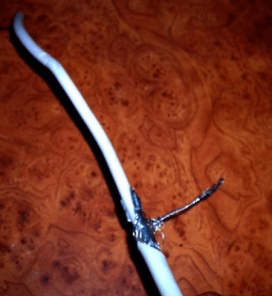
We strip 1.5 - 2 cm at both ends, twist the two loops behind each other, and then solder the joint. This will be one cable connection pin. After 2 cm another. It doesn’t matter where to solder the central core or the braid.

Solder spacing 2 cm
I took about three meters of cable. In most cases, it’s enough if you don’t do it for yourself personally. For yourself, measure out as much as you need.
I stripped the cable from the antenna side by two centimeters, to the plug - 1 cm. If the plug is like in the photo. You can take any, stronger.

Stripping the cable
The plug was cleaned with a file and a scalpel.

After sealing, both soldering points are filled with glue from a gun. On the plug, first hot glue is poured into the soldering area and into the plastic cap, with a reserve; the excess can then be removed. Then, before the glue cools down, everything quickly comes together. You can’t gnaw such a joint with your teeth. Reliable, at the same time elastic.
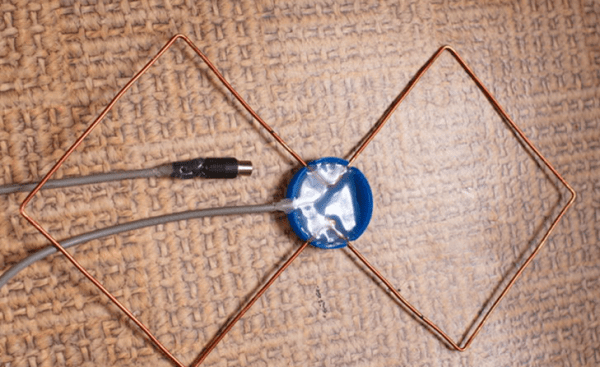
The soldering on the antenna itself is also filled with glue, but for the rigidity of the structure, a frame is taken - any lid, box, .... I took the cap from a 20-liter water bottle, of which I had accumulated a sufficient amount. If you are making an antenna like me for mass production, then it is better to immediately use common materials that are literally lying under your feet for better repeatability of the antenna. If the antenna is made in a single copy for quick riveting, then you don’t have to fill anything at all.

The result is such a design that can be stuck anywhere - on a cornice, on a curtain, on a window frame. To do this, you can carry with you a piece of wire, a couple of screws, a couple of pins...

Antenna assembly
If the antenna is dented during transfer, it can be easily and without damage aligned. This is perhaps its main advantage.
I don’t always carry this design with me, but only when I receive a specific order to connect a DVB-T2 digital television tuner. It fits easily with the tool in my backpack.
It is more convenient to make several antennas at once. Takes less time.
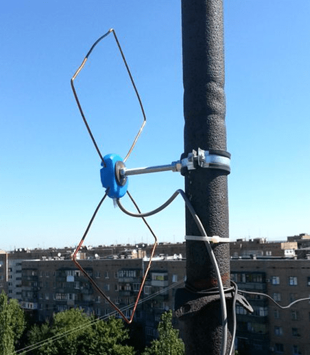
This is how my friend fixed the antenna, using it as an outdoor one. The tower is about 9 km away. Reception is reliable despite the simplicity of the antenna.

Today we are sharing life hacks on how to make a TV antenna with your own hands. An antenna is a device for emitting or receiving radio waves. There are transmitters, receivers and transceivers. The editors learned that a simple design can be made using copper and brass wire, copper tubes, wires, and even tin cans.
TV antenna made from tin cans
You can make an antenna for a TV yourself, from scrap materials, even from empty beer cans. This method is the fastest and easiest. You can make a structure from electrodes and disks. The maximum number of channels will be seven.
You will need:
- can;
- plug;
- antenna cable;
- screwdriver;
- adhesive tape or insulating tape;
- wooden trempel;
- self-tapping screws (2 pcs).

The indoor design guarantees reliable reception of an analog signal within the city and without cable coordination (with a length of up to 2 m).

Distance between banks:
where λ is the wavelength. There should be no more than 3-4 dipoles. If there are fewer of them, the gain will be insignificant; if there are more, there will be problems with cable matching.
The signal quality will noticeably improve if you place a metal mesh screen on the back.
Distance between screen and main structure:
How to make a design:
How to improve the antenna?
An amplifier is needed if the broadcaster is located far away. With an amplifier, the design receives the signal more reliably, but the “do it yourself” option may not work here.
You can use a magnet onto which several turns of television cable will be wound (collected both near the TV and on the antenna).
If the question is how to strengthen the signal of a home structure so that instead of 7, 20 channels are clearly broadcast, you need to:
- buy a special TV signal pre-amplifier;
- find the location of ideal signal reception;
- get rid of interference caused by metal objects.
How to quickly make an antenna:
How to assemble an antenna for digital TV?
A homemade design should be:
- carefully manufactured with a high degree of precision without loss of signal power;
- strictly directed along the axis of the electromagnetic wave emanating from the transmitting center;
- targeted by type of polarization;
- have protection from side interference signals of the same frequency emanating from any sources: electric motors, radio transmitters, generators.
How to make your own antenna for digital TV (DVB T2):
Simple digital TV antenna: what are your options?
It will require a piece of coaxial cable with a characteristic impedance of 75 Ohms and a plug to connect the structure.
The algorithm is like this:
- use a regular knife to cut off the outer shell from the free end;
- take the length with a small margin, since it is easier to bite off a small piece during setup than to run for a new cable;
- the shielding layer is removed from this section of the cable, the inner core is exposed and the insulation is removed;
- insert the plug socket into the connector on the TV signal set-top box, direct the exposed wire of the inner core across the incoming electromagnetic wave;
- remember horizontal polarization;
- the on-air digital antenna should be fixed on the windowsill or with a piece of tape on the glass;
- interference and reflected signals are shielded by a strip of foil located at a short distance from the central core;
Types of antennas and which ones can you make yourself?
There are “Polish”, “eight” and “square”. Digital antennas for the TV tuner and set-top box must be set to the same frequency.
IMPORTANT! Both the set-top box and the tuner must be able to decode the signal.
"Polish" antenna and digital TV
It provides high-quality and reliable reception of analog television (+ UHF), but is completely unsuitable for receiving modern digital TV.

"Eight": manufacturing algorithm
A simple design for DVB T2, which can be made from Ø 3 mm copper wire. The reflector is not used in this case. The upper side of the segments is 14 cm, the side is 13 cm.
We measure the wire 112 cm long and begin to bend:
- We bend the 1st segment to a length of 14 cm (for the antenna - 13 cm and 1 cm - for the strength of the loop);
- 2nd and 3rd, like 6 and 7 – 14 cm;
- 4th and 5th – 13 cm;
- 8th – 14 cm – 13 cm and 1 cm – with a strength loop.
We clean the loops, tighten them and solder them - they will become contacts for connecting the cable. For soldering, we strip the cable from the antenna side by 2 cm and 1 cm from the plug side, the joints are sealed with any elastic hot-melt adhesive.
What is a “square” and is it worth taking on it yourself?
A modification of the “three square” design with 6 elements and a transformer confidently receives digital and analogue channels at a distance of up to 10 km of line of sight.
- Double square
Behind the main frame is a reflector, the side of the main frame is 0.254λ, the side of the reflector is 0.278λ, the distance between the frames is 0.089λ.

Another option for a double square is two rings.

Butterfly antenna
A short-wave, small-sized antenna, shaped like a butterfly. To make it, you need copper wire with a diameter of about 2 mm; for external use, 4 mm is allowed; for home use, a regular 75 Ohm TV coaxial cable.
Rectangular wire frame (length and width):
- for TV - 500x200 mm;
- for Wi-fi (omnidirectional) and Bluetooth - 90x30 mm.
We twist the frame crosswise and cut it with wire cutters so that two triangles are formed. We solder the coaxial cable and secure it with staples (adhesive tape) to an ebonite, wood or plastic dielectric.
Powerful TV Antenna: What should I know about it?
In order for the device to function like a regular antenna, its receiving circuit must be improved.
Algorithm:
- we buy equipment to strengthen the signal;
- connect to the device to eliminate signal interference;
- wrap the cable at both ends with insulating tape;
- we make a screen for high-quality reception: a kind of metal mesh, which is isolated from the TV and fixed behind the receiver;
- for the screen, an ordinary metal mesh from an ordinary fence will do;
- add iron rods and connect them symmetrically to the screen to amplify the signal (it is necessary that the entire structure be made of the same type of metal to avoid oxidation) $
- We place another amplifier in the center of the installation and solder the contacts to the receiver.
IMPORTANT! This television structure is installed on the roof with a focus on the nearest television tower.
Universal design
Required tools and materials:
- copper wire (length 4 m, cross section 4 mm2);
- board of any thickness, but 7 cm wide and 55 cm long;
- soldering iron;
- wood screws;
- tape measure or ruler;
- screwdriver;
- simple pencil.

Algorithm:
- cut the copper wire into 8 parts, each length 37.5 cm;
- remove the insulating layer in the middle part of each of the resulting parts of the wire;
- cut off 2 more copper wires (22 cm each) and divide them roughly into 3 equal parts;
- at the points of inflection, remove the insulating layer;
- bend the wire in prepared (bare) places;
- the distance between the ends of the wire bent in half is 7.5 cm;
- secure the plug, connect the television cable.
How to make an antenna for digital TV (DVB T2) yourself:
Log-periodic (all-wave) design
This is a collecting line with halves of dipoles installed on it alternately. The length of the piece of wire forming the half-dipole will be equal to λ/4.
IMPORTANT! Do-it-yourself outdoor structures can provide a gain of up to 25 dB, and about 12 dB for indoor ones.

LPA is an ideal device for receiving both analogue and digital signals. To calculate the parameters, it is necessary to know the value of the progression index (from 0.7 to 0.9) and the opening angle α (30-60°). We take the proportion as a basis and calculate the necessary parameters:
τ=B2/B1=B3/B2=Bn/(B(n-1)) = A2/A1=A3/A2=An/(A(n-1))
The higher τ, the better the gain indicator. Reducing the angle α can increase directivity.
Calculation of parameters:
- determine the values of B2 and A2;
- calculate B1 and A1 and other parameters.
What types of antennas are there? Home simple homemade antenna
The home structure is mounted from copper or brass wire. Aluminum is not suitable because it oxidizes quickly.
The wire is cleared of insulating material at both ends, one end is attached to a pipe or battery, and the opposite end is inserted into a television connector. The amplifier of the required frequencies is a pipe that runs through the entire house and goes upstairs. A signal appears immediately, the antenna picks up 5 channels.
- For an apartment with a balcony
A longer wire is taken, since the TV and the balcony area will need to be connected. The wire is stripped on both sides, one end is connected to the TV in a cable socket, and the other is pulled out onto the balcony and attached to ropes or strings. Such an antenna gives a cooler image, and there are more channels with it.
Antenna for a summer residence
Passive structures are installed to ensure stable signal reception at a distance of up to 30 km in both winter and summer. For longer distances, more powerful designs are needed, preferably with an amplifier. For hilly terrain and ultra-long-range reception, the antenna must be raised higher using a mast.
For a classic garden design you will need:
- wire (Ø 1.5 mm) - at the rate of 1.5-2 m for the antenna and 5-6 m for the distance from the structure to the TV;
2. the outer part is made of prepared wire (twist 1-1.5 m into a ring, Ø from 356 mm to 450 mm); - the inner part of the antenna (make a second ring from wire, dimensions - 180 mm;
- the finished rings - the basis of the future antenna - are fixed on a piece of plywood (you can also use a piece of wood), but so that the wood does not overlap the rings and does not dangle;
- Orient the finished structure with its rings in the direction of the signal source, and rotate the antenna to search for the best signal.
Antenna Kharchenko (biquadrat)
This is an outdoor zigzag design with a reflector.

Z-antenna system with reflector provides the same parameters as
LP antenna. The difference is in the main lobe - it is twice as long horizontally, which allows you to catch a signal from all directions.

The UHF antenna is made of a copper tube and a 6 mm thick aluminum sheet.
Car antenna: internal and external
- Internal
You will need a frame device, which is placed at the back under the glass seal. It is narrowed at the top, but the dimensions are not what is required at a frequency of 27 MHz. For this reason, a capacitor is installed in the center, with the help of which the TV antenna for a car is tuned to resonance on the required channel.
IMPORTANT! There are several receiving frequencies - 27 and 65 MHz, 28.2 and 68 MHz.

Manufacturing algorithm:
- we take wire MGTF 0.5, which is laid along the edges of the rear window in the form of a trapezoid;
- do the same with the upper part;
- the poles are positioned so that it is easy to add wires for the matching capacitor;
- to pick up the signal, use cable RK-50;
- 5-25 PF are fixed in the center of the rear window, to which both cables are directed strictly vertically.
Universal compact TV antenna for a car:
- External
For a good signal, you need to attach a pair of telescopic antennas from the radio. The case can be taken from a Polish device.
 Figure 11 - Polish design - the basis for an internal auto antenna
 Power supply to amplifier:
- take the connector for the active TV antenna and solder the wire to it;
- We pass the cable from the TV antenna so as not to pinch it;
- screw it to the connector;
- the wire soldered to the connector is connected to output +12 on the radio to turn on the amplifier or active antenna.
There are active interior combined TV antennas with external elements for receiving MF/UHF.
In addition to the above, there are meter (crossed aluminum tubes) and fractal antennas.
DIY fractal Wi-Fi antenna:
IMPORTANT! All stories about the effective operation of a mercury antenna are a big misconception. Science does not know a single principle by which a mercury antenna could work. The editors warn that making a mercury antenna yourself is a so-so idea and a dangerous undertaking.
What is digital TV multiplex?
A digital multiplex is a set of channels of the same frequency. There are two multiplexes: the first is available in all cities with digital TV, but not all towers are ready for the second. For installation you will need a receiver and antenna supporting DVB T2.
The population receives the bulk of information through television, viewing of which requires a receiving antenna. You can buy a receiving device at any store, but this is not always possible. In this case, you can make an antenna with your own hands. Next, the main varieties and the order of their assembly will be considered.
The main advantage of homemade devices is that they require a minimum of financial costs. It also happens that homemade options are superior to factory ones in many respects.
The advantage is that handicrafts can be called “all-wave”; this is not done intentionally, it turns out just like that. The disadvantages of homemade devices are their unaesthetic appearance, although this depends on the hands of the master. A significant disadvantage is the inaccessibility of some materials.
Undoubtedly, there are more advantages, so let’s look at the main handicrafts.
Varieties
"Beer"

To make the product you will need an even number of beer cans. The most common options are made of two pieces. The installation process is quite simple and requires a minimum of tools and consumables.
Instructions:
- To begin with, take a wooden strip(a hanger will also do), which will serve as a support for the structure.
- Beer cans are attached to the rail using tape, at a distance of about 6 centimeters.
- Next, a television cable is attached to the banks. The procedure can be performed using either self-tapping screws or solder.
- The last step is to attach the base to the mast and adjust the position. A more complex version is made from 6-8 cans. Such an antenna will require two bases installed vertically.
- 4 cans are attached to the installed bases, parallel to each other.
- Using a copper plate or wire, you should connect the cans, located on one rack, then perform the procedure on another.
- The next step is to install the racks into one structure, it should be taken into account that the distance between the bottoms of the cans must be at least 60 mm.
- It remains to secure the cable at the extreme points connecting plates.
Antenna with minimal costs

It should be remembered that television travels in space in the form of waves that are well perceived by metal objects. To watch several TV channels, you can use a piece of wire, one end of which is attached to the heating system, and the other into the TV to the central contact.
The principle of operation of such an antenna is based on the area of the system, and it envelops almost the entire house at different heights. The reception quality of the design is not the highest. A more interesting option requires a balcony with metal strings for laundry.
The assembly technology is completely similar to the battery system. There are places with reliable signal reception, where you can use a knitting needle, which will make it possible to view the main channels.
Regular antenna

Assembling the antenna yourself is quite simple; you will need a tube made of aluminum or brass. The latter option is more convenient, since this material practically does not oxidize.
Instructions:
- The length of the tubes should be 276 mm– it is this that ensures the reception of most channels, thickness 20 mm. The tubes should be flattened on one side, then holes should be drilled in these places.
- The next stage is preparing the base. It must be made of dielectric material, measuring 150 by 50 mm and at least 5 mm thick.
- Next, a mock-up of the antenna is laid out on a flat surface. The base is laid, the tubes are placed on top of it, the distance between the flattened ends of the tubes is 65 mm, the locations of the holes in the tubes are marked and a hole is made in the base with a drill of the same diameter.
- The next stage is the assembly of the structure. The tubes are attached to the base using bolts; it is advisable to use an additional fastening in the form of a clamp - this will ensure the strength of the structure. The bolts used for fastening are 15-20 mm long, this is necessary for fastening the loop.
- Antenna assembly completed, all that remains is to connect the cable; you cannot do this directly to the antenna. The correct connection is made through a ring of wire with a resistance of 75 ohms. The length of the loop is calculated individually depending on the length of the tube; in this situation it is 280 centimeters.
The outlet cable is already connected to the loop.
Powerful antenna

Having dealt with the classic options, you should consider antennas designed to receive the weakest signal. To create one, you will need a minimum of materials, namely a brass tube, a plate of the same material, desire and hands.
Instructions:
- The manufacture of the receiving device begins with bending two squares of the same size from the tube, mounted on a dielectric base in such a way that the distance between the corners of the squares is 10-15 mm.
- The next step is making the screen, designed to strengthen the signal power and smooth out radio interference. The screen is curved in the shape of a rectangle 11x10 centimeters, with a side height of 23 mm and a width of 6 mm.
- When connecting two components, a distance of 12 mm must be maintained. The finished product is connected to the TV using a cable with a resistance of 75 Ohms. An important fact is that this design does not allow the use of bolted connections, only solder is allowed.
When assembled correctly, the model outperforms its factory counterparts.
UHF antenna

Digital television is covering more and more territories, but for its reliable reception a special module is required. Often, the device is purchased separately, but there are TVs that have a built-in module.
But one receiver is not enough; you need an antenna that receives UHF waves. The simplest option is made on a sheet of plywood.
Instructions:
- For assembly you will need a 75 Ohm TV cable 53 cm long. This segment is fixed on the sheet in the shape of a ring; it can be secured either with clamps or with glue.
- When bending the loop, make sure that there is a gap of 5-10 mm between the ends of the cable. The second element of the product is made from a similar cable, 15.5 cm long, from which a loop is made.
- The connection between the ring and the loop is as follows– the inner core of the ring is connected to the winding of both sides. The loop of the central conductor is attached to this twist, and the outer winding is connected between the edges. The central core of the antenna cable is connected to the inner core of the loop, and the winding is connected to the loop winding.
Settings
Installation of do-it-yourself products is carried out similarly to factory-made analogues. Most options require a mast to raise them to maximum height.
In most cases, a height of 2-3 meters higher than the height of the roof of the building is sufficient. Additionally, when installing, you should choose a place with the strongest signal, this is especially true for indoor devices.
Configuration is carried out by rearranging or rotating the antenna towards the tower; sometimes it is necessary to install an additional screen on the rear side.
DIY amplifier
 There are often situations when a properly assembled and well-tuned antenna refuses to reliably receive a signal, then you simply cannot do without a signal amplifier.
Most of these devices have a complex design, which is difficult to assemble without certain knowledge. A simpler version can be made with your own hands in 10 minutes.
You will need a magnet onto which several turns of television cable are wound. This device can be assembled either near the TV or on an antenna. The latter option is most popular in factory amplifiers.
Results

Concluding the topic, you should pay attention to the fact that the highest quality of reception can be achieved by using soldering (bolts and nuts oxidize, significantly deteriorating the signal). An important aspect is the correct choice of cable. The most popular option is a product with a resistance of 75 Ohms, made of silicone.
Such products have a long service life, plus they are not affected by climate. The way you connect the cable to your TV is important. It is recommended to use special plugs; solderless options are allowed.
Before starting to assemble the product, you need to decide on the type of product; to do this, you should find out the frequency at which the signal is broadcast, this depends on the specific area.


