About the motion sensor and connecting it to the Arduino. Creation of a security alarm with a motion sensor based on Arduino and infrared sensors Alarm on Arduino with a siren
Spring, as you know, is accompanied by all sorts of aggravations, and now the main "aggravation" crawled out of its holes into the street in order to appropriate for itself what does not belong to it. This means that the topic of protecting one's property becomes more relevant than ever.
The site already has several reviews on homemade -. They are functional, of course, but they all have common feature- depending on the outlet. If this is not a problem with real estate where electricity is already connected, then what about property where the outlet is far away or the surroundings are completely de-energized? I decided to go the other way - to assemble a long-lived, as simple as possible and independent of mains power device, which will sleep all the time, and when robbers enter, it will start up and call back to the owner’s phone, signaling with a simple alarm call.
Review Items
Purchased:1. Bread board one-sided 5x7 cm: getinaks- or fiberglass
* - fiberglass is much better than getinaks.
2. Module Neoway M590 - , with PCB antenna -
3. Arduino Pro Mini "RobotDyn" ATmega168PA 8MHz 3.3V -
4. Lithium charge-discharge control board -
Obtained from the ruins of civilization:
1.
Racks for the board, sawn from the cases of devices - 6 pcs.
2.
Lithium flat battery 1300mAh
3.
Staples used to fix the cable to the wall
4.
Stationery eraser
5.
Copper wire 1.5mm thick
6.
Instrument case from the local radio market - 1.5$
7.
Pair of LEDs different color(taken from a VHS player)
8.
Antenna and button with a cap (taken from a Wi-Fi router)
9.
4-pin terminal block (taken from a dimmer)
10.
Power connector (taken from an old charger for 18650)
11.
6-pin connector (taken from a DVD drive)
12.
Can(from under coffee for example)
Arduino Pro Mini "RobotDyn" Atmega 168PA 3.3V 8MHz
Specifications:Microcontroller: ATmega168PA
Operating voltage direct:.8 - 5.5 V
Operating voltage through the stabilizer LE33: 3.3 V or 5 V (depending on model)
Working temperature:-40°C… 105°C
Input voltage: 3.35-12V (3.3V model) or 5-12V (5V model)
Digital Inputs/Outputs: 14 (6 of which can be used as PWM outputs: 3, 5, 6, 9, 10, and 11)
Analog inputs: 6
Timers-counters: two 8-bit and one 16-bit
Power saving modes: 6
DC current through input/output: 40 mA
Flash memory: 16 KB (2 used for bootloader)
RAM: 1 Kb
EEPROM: 512 bytes
Memory write/erase resource: 10,000 Flash/100,000 EEPROM
Clock frequency: 8 MHz (3.3V model) or 16 MHz (5V model)
SPI: 10 (SS), 11 (MOSI), 12 (MISO), 13 (SCK)
I2C: A4 (SDA) and A5 (SCL)
UART TTL: 0 (RX) and 1 (TX)
Datasheet:
The choice fell on this atmega quite by accident. on one forum where energy-efficient projects were discussed, in the comments I got advice to use exactly the 168th atmega.
However, I had to tinker to find such a board, since very often all the lots were inundated with 328 atmegas at a frequency of 16 MHz, operating from 5V. For my project, such characteristics were redundant and inconvenient from the very beginning, the search became more complicated.
As a result, I came across a 3.3-volt version of the Pro Mini on Atmega 168PA on eBay, and not just a Chinese one, but under the RobotDyn brand from a Russian developer. Yes, I, too, at first, like you, had a grain of doubt. But in vain. When the project was already assembled, and AliExpress introduced a mandatory paid delivery for cheap goods (after which parcels began to be lost much more often), then later I ordered a regular Pro Mini Atmega168 (without PA) 3.3V 8MHz. I experimented a little with power saving modes with both boards, flashing into each a special sketch that immersed the microcontroller in the maximum power saving mode and this is what happened:
1) Arduino Pro Mini "RobotDyn": ~250uA
2) Arduino Pro Mini "No Name": when power is supplied to the voltage regulator (RAW output) and the LED is soldered, the current consumption is ~3.92mA

- as you understand, the difference in power consumption is almost 16 times, all because NoName's Moscow Pro Mini uses a bunch of Atmega168 +, of which the MK itself eats only 20uA current (I checked this separately), all the rest of the gluttony falls on the AMS1117 linear voltage converter - the datasheet only confirms this: 
In the case of the board from RobotDyn, the connection is already somewhat different - this is Atmega168PA + - another LDO stabilizer is already used here, whose characteristics in terms of energy saving turned out to be more pleasant: 
I did not solder it, so I cannot say how much current the Atmega168PA consumes in its pure form. In this case, I had ~250uA when powered by a Nokia lithium battery. However, if you unsolder the AMS1117 with the NoName "of the Moscow board, then the ATmega168 is ordinary, in its pure form, as I said above, consumes 20uA.
Power LEDs can be knocked off with something sharp. It's not a problem. The stabilizer was soldered with a hairdryer. However, not everyone has a hair dryer and the skills to work with it, so both of the above options have a right to exist.
Neoway M590E module
Specifications:Frequencies: EGSM900/DCS1800 Dual-band, or GSM850/1900 or Quad-band
Sensitivity:-107dBm
Maximum transmission power: EGSM900 Class4(2W), DCS1800 Class1(1W)
Peak current: 2A
Working current: 210mA
Sleep Current: 2.5mA
Working temperature:-40°C… +85°C
Operating voltage: 3.3V…4.5V (recommended 3.9V)
Protocols: GSM/GPRS Phase2/2+, TCP/IP, FTP, UDP etc.
Internet: GPRS CLASS 10
Datasheet:
The cheapest GSM module that can be found on the market, usually second-hand, soldered by not always dexterous Chinese hands from the equipment. Why not always smart? Yes, all because of soldering with a hairdryer - often these modules come to people with a shorted plus and minus, which is one of the reasons for their inoperability. Therefore, the first step is to ring the power contacts for a short circuit.
Note. I would like to note a separate, important, in my opinion, point - these modules can come with a round coaxial connector for the antenna, which allows you to separately order a more serious antenna and connect it to the module without dancing with a tambourine. And they can come without this connector. This is if we talk about the cheapest sets. If you don’t want to rely on a lucky chance, then there are sets that are a little more expensive, where this connector is present + the kit comes with an external antenna on a textolite board.
This module is also capricious before power supply, since at its peak it consumes up to 2A current, and the diode that comes with the kit seems to be designed to lower the voltage from 5V (which is why it is written on the board itself 5V) to 4.2V, but judging by according to the complaints of the people, he creates more trouble than good.
Suppose you have already assembled this module, and a jumper is soldered instead of a diode, since we are not going to supply a voltage of 5V to it, but we will power it directly from a lithium battery, which falls within the allowable voltage of 3.3-4.2V.
It will be necessary to somehow connect it to the computer, and check for operability. For this case, it is better to buy ourselves in advance - through it we will communicate with the Arduino module and boards via the UART (USART) serial interface.
The connection is shown below in the picture (I drew it as best I can):
TX modem >>> RX converter
RX modem<<< TX конвертера
Battery Plus - Modem Plus
The minus of the lithium battery is combined with the GND of the modem and the GND of the converter
To start the modem, connect the BOOT output through a 4.7 kΩ resistor to GND

In the meantime, run the program on the computer. Pay attention to the settings:
1) Select the COM port to which the TTL converter is connected, in my case it is COM4, yours may be different.
2) Select the baud rate. (There is a nuance here, because the modules themselves can be configured for different speeds, most often 9600 baud or 115200 baud. Here you need to select empirically, choosing some speed, connecting, and sending the AT command, if cracks come in response, then it will turn off , select a different speed and repeat the command until the answer is OK).
3) Select the packet length (in this case 8 bits), parity bit disabled (none), stop bit (1).
4) Be sure to tick +CR, and then a carriage return character will be automatically added to each command we send to the module at the end - the module understands commands only with this character at the end.
5) Connection, everything is clear here, clicked and we can work with the module.

If you click on "Connection" and then start the module by applying BOOT through a 4.7K resistor to the ground, then first the message "MODEM:STARTUP" will be displayed in the terminal, then, after a while, the message "+PBREADY" will be displayed, which means that the phone number has been read. book, even though it may be empty: 
Under this spoiler AT commands with examples
We print the AT command - in response, the module sends us our command, since the echo mode is enabled, and OK: 
Let's check the status of the modem with the AT + CPAS command - in response, our team again, + CPAS: 0 and OK.
0 - means that the module is ready to work, but depending on the situation, there may be other numbers, for example, 3 - incoming call, 4 - in connection mode, 5 - sleep mode. I couldn't find any info on 1 and 2. 
Changing the data transfer rate via UART occurs with the command AT + IPR = 9600 - this is if you need a speed of 9600. If some other, similar to AT + IPR = 19200 for example or AT + IPR = 115200. 
Let's check the network signal. AT + CSQ, + CSQ comes in response: 22.1 - the value before the decimal point has a range of 0 ... 31 (115 ... 52 dB) - this is the signal level, the more, the better. But 99 means its absence. The value after the decimal point - signal quality 0 ... 7 - is the opposite here, the smaller the number, the better. 
Let's turn off the echo mode by sending the ATE0 command so that duplicate commands do not interfere. This mode is switched back on with the ATE1 command. 
View AT+GETVERS firmware version 
These and many other commands can be viewed
Board Combination
If Pro Mini is not difficult to solder to a breadboard, then with a GSM module the situation is somewhat more complicated, because. its contact comb is located only on one side, and if only it is soldered, then the other side of the board will simply hang in the air. Then, again, by eye, I had to drill additional 3 holes near three corners on the board. The areas around each of the holes were then de-masked. For convenience, I placed the disconnected leads from the comb on the solderless breadboard (white) and, having installed the GSM module board on them, normally soldered:
Later I had to make another hole, in my case on the letter "I", where it says "Made In China", on the edge of the board. 
It so happened that the added contact, which is essentially GND, became close to the GND of the Pro Mini board, and thus it became possible to combine the ground of the GSM module and the Pro Mini with a drop of solder (a long lead in the middle and to the right of it is the Pro Mini lead) - marked them with arrows. It turned out crooked, of course, but now it holds securely: 

There was some space left between the boards - I placed a lithium discharge charge control board with a pre-soldered microUSB connector and soldered wires in it. 
The scarf enters there very tightly, while the glow of the LEDs on the side will be clearly visible through a small hole in the case. 

Board racks
To securely fix the board inside the case, I had to spend a couple of days thinking about how this could be implemented. The option with hot melt adhesive was not considered for several reasons - it can fall off, deform, and most importantly, the design would turn out to be difficult to disassemble.I came to the conclusion that the simplest and most correct option here would be to use racks, which naturally I did not have. However, there were a couple of non-working chargers, from where one long rack with a thread for self-tapping screws was cut out. Each rack was sawn in half and finished with a file to about 9.5mm - it is at this height that the battery located under the board has a sufficient margin, about 2mm - this is done so that the soldered contacts of the board do not touch it with their tips and so that it is possible to put a piece between them foam for fixation.
As for attaching the board directly to the case, here I cut four strips from a coffee can, drilled a hole at the ends of which, then fixed them on the same self-tapping screws that are screwed into the racks. See the photo below to see how it looks.
The next step is to screw a pair of stands on the other side of the board, that is, from above, so that when the case is closed, the lid rests slightly against these stands, creating additional fixation. A little later, under this case, I came across a building from under the Soviet propaganda radio (if it had been found earlier, I would have taken all the racks from here), where I found a couple of more or less suitable heights, but first I drilled them in the center with a drill under self-tapping screws. Then he cut them down and also finished them off with a file, removing the excess. Here I got one subtlety - in the photo you can see that one white stand is screwed to the getinax board from the edge, and the other white stand is directly to the module board, because. from one edge, the modem board completely covers the bottom board, and from the opposite edge, on the contrary, the bottom one looks out. At the same time, holes had to be additionally drilled in both boards so that the heads of the self-tapping screws could pass freely.
And finally, it remains to make sure that the board is always parallel to the case - the brackets that are used to fix wires and cables on the wall fit perfectly under this case, I previously removed the nails from them. The brackets cling well to the board with their concave side without any additional devices, the only thing is to the right of the SIM card, the width of the bracket turned out to be excessive and had to be sanded as well.
All the details were adjusted by eye and empirically, below is a photo of all of the above:


Connectors. LEDs. Button.
Since I ran out of comb, I had to dismantle the 6-pin connector from the DVD drive board, which I then soldered to the Pro Mini, this is for the convenience of flashing the board. Nearby, I soldered a round connector (Nokiev 3.5mm) for charging lithium.
The body of the 6-pin connector was slightly finished with a file, because its edges protruded slightly above the body. The charging socket fits perfectly into the wall of the case. 
On the other side of the board, I soldered a button to reset the device and two LEDs for debugging the firmware - the red LED is connected to the GSM module, the second green LED is connected to the 10th output of the Pro Mini - it's easier for me to debug the program. 
Battery upgrade
A flat Nokian battery from Nokia phones is no less common than the 18650, but many simply refuse to use it because of the inconvenience of connecting contacts that are recessed deep into the battery itself. It is undesirable to solder them, so it was decided to use the method proposed by these, namely, to make a contact block from a stationery eraser and copper wire (1.5 mm thick).First, I pierced a piece of eraser with two wires with previously stripped ends, and figured it out to the battery contacts so that the distance between them coincided,
he bent the ends, tinned them with a soldering iron, and pulled them back a little by the long ends so that the resulting contacts were sunk into the eraser.


Battery example: 
You can fix the terminal block with a rubber band or wrap it with blue electrical tape, which I did in the end. 
Assembly.
The main part of the work is done, it remains to collect and fix it all.Between the battery and the board, I put a piece of foam rubber so that it would not crawl inside the case later. I additionally soldered a 2200 uF capacitor to power the module.

When charging is connected: 
Frame. External terminal block.
The case got on the local radio market for about $ 1.5, if translated into dollars, 95x60x25mm in size, almost the size of a pack of cigarettes. I drilled a few holes in it. First, for a 4-pin terminal block taken from a non-working dimmer.I completely freed the two extreme contacts from bolts with gaskets, drilled holes for longer bolts, on which the entire terminal block will be held on the case. On the case itself, of course, the two extreme holes will be large, and the two in the middle will be smaller - they will have contacts threaded through them, one of which is connected to the VCC Pro Mini, and the second contact to pin 2.

Drilling holes, although simple at first glance, is no less time consuming, it is very easy to miss, so I did it first with a smaller diameter drill, then a larger one. 
For the clock button, I picked up a cap with a slightly concave top, so that through a narrow hole in the case it was convenient to hit it with a match or a paper clip. 
Board in a case with a connected USB-TTL converter cable: 
About the antenna.
The antenna, as you may have noticed in the course of the review, was constantly changing, as I experimented with different homemade antennas. Initially, there was a round coaxial connector on the module board, but on the fifth time it was used for an external antenna, it simply fell apart, so keep in mind that it is flimsy. As a result, I tore out the textolite antenna from the old router, and soldered it to the module board, because. it catches the net a little better than the spring and wire. 
Well, completely assembled with the connected charging looks like this: 
Test. How it works:
In addition to tests with antennas, I checked how the alarm would behave on the street, in frost -15. To do this, I simply placed the entire insides in a container and left it on the balcony for the night, while the alarm did not start, the reason turned out to be generally obvious - lithium does not like frost. This was confirmed by another test, where I left the battery at home, and brought the board through long wires to the street and left it like that for a day in the same frost - operation, as if nothing had happened. On the other hand, it would be strange if the alarm did not work. in the datasheets for atmega, for the module, for quartz - the allowable operating temperatures are up to -40 degrees.
The principle of operation is organized by an external interrupt, initially pin 2 is closed to VCC and thus a logical 1 is maintained on the output, and the controller is sleeping. As soon as the contact is broken and 0 appears on pin 2, the microcontroller wakes up, lowers the 3rd pin (to which the modem BOOT is connected through a resistor) to the ground - the module starts, the MK periodically polls the module for readiness, and as soon as it catches the network, it immediately sends a call to the owner's phone number specified in the code. After rejecting the call, the device turns off without sending more endless calls than many Chinese alarms sin.
Additional Information
#include
Diagram (without charge-discharge control board) 
Conclusions and thoughts. Plans.
The alarm is used in the country, I am satisfied with the work, however, with further study of the AVR, more and more ideas come up for its further modification. Arduino with its pseudo-language Wiring upset me a lot, because. There was one unpleasant moment in the work. When I used the functions to work with the digitalWrite(); ports; or pinMode(); - then the GSM-module for some reason very often hung up. But it was worth replacing them with tricks like DDRB|=(1<For energy saving...
The assembled device worked for four full months without recharging and continues to work, although it’s more correct to say “sleep”. This is checked by a simple reboot through the white button. With a power consumption of 250 μA (through the LE33 stabilizer) and a battery of ~1430 mAh, although okay, due to the non-newness of the battery we will round up to 1000mAh, it turns out that the device can sleep for about 5.5 months without recharging. If you still unsolder the stabilizer, then the operating time can be safely multiplied by 10 times. But in my case, there is no need for this, because you still need to spend the balance from the SIM card every three months, at the same time the device can be checked and recharged.
The example of energy saving given in the review is far from the limit, because. judging by the information from the datasheet, it is possible to lower the clock frequency of the microcontroller (and this is done by installing fuses) to 1 MHz and, if 1.8V voltage is applied, then the consumption will drop below the 1 μA bar in active mode. Very foolish! But if the MK is clocked from the internal RC generator, then another problem will appear - the UART ether will be clogged with garbage and errors, especially if the controller is heated or cooled.
Upon completion...
1)
A conventional wire set to break is not very convenient, I plan to experiment with a Hall sensor and a reed switch, although they say about the latter that it is not very reliable, because the contacts inside it can stick.
2)
It would be nice to add the ability to change the "owner number" without the participation of a computer and flashing. This already with EEPROM will have to work.
3)
Try interrupts from the watchdog timer, but not just for the sake of curiosity, but for the microcontroller to periodically wake up by itself, measure the battery voltage and send the resulting value via SMS to be aware of how low the battery is.
4)
A solar panel can completely eliminate the need to recharge the device, this will be especially true for low-capacity batteries.
5)
For a long time I wanted to buy LiFePo4 batteries, which, according to reviews, normally tolerate frost, but while I was looking for a suitable lot, spring had already imperceptibly come.
6)
Work on the aesthetic component
Which Pro Mini should I buy?
If there is no hair dryer, then Pro Mini "RobotDyn" Atmega168PA 3.3V, pick up the LED with something sharp and have ~ 250 μA.
If there is a hair dryer, then any board, solder the stabilizer and the power LED - you get ~ 20 μA of current consumption.
That's all for now, I hope the review was interesting and useful.
I plan to buy +174 Add to favourites Liked the review +143 +278Infra-red (IR) sensors are usually used to measure distances, but they can also be used to detect objects. By connecting several IR sensors to the Arduino, we can create a burglar alarm.
Review
Infra-red (IR) sensors are usually used to measure distances, but they can also be used to detect objects. IR sensors consist of an infrared transmitter and an infrared receiver. The transmitter emits pulses of infrared radiation while the receiver detects any reflections. If the receiver detects a reflection, it means that there is some object in front of the sensor at some distance. If there is no reflection, there is no object.
The IR sensor we will be using in this project detects reflections within a certain range. These sensors have a small linear charge-coupled device (CCD) that detects the angle at which IR radiation returns to the sensor. As shown in the figure below, the sensor transmits an infrared pulse into space, and when an object appears in front of the sensor, the pulse is reflected back to the sensor at an angle proportional to the distance between the object and the sensor. The sensor receiver detects and outputs the angle, and using this value, you can calculate the distance.
By connecting a couple of IR sensors to the Arduino, we can make a simple burglar alarm. We'll put sensors on the door frame, and by properly aligning the sensors, we'll be able to detect when someone walks through the door. When this happens, the output of the IR sensor will change, and we will detect this change by constantly reading the output of the sensors with the Arduino. In this example, we know that an object passes through the door when the IR sensor output exceeds 400. When this happens, the Arduino will trigger an alarm. To reset the alarm, the user can press the button.
Accessories
- 2 x IR distance sensor;
- 1 x Arduino Mega 2560
- 1 x buzzer;
- 1 x button;
- 1 x 470 ohm resistor;
- 1 x NPN transistor;
- jumpers.
Connection diagram
The circuit for this project is shown in the figure below. The outputs of the two IR sensors are connected to pins A0 and A1. The other two pins are connected to the 5V and GND pins. A 12 volt buzzer is connected to pin 3 via a transistor and a button used to disable the alarm is connected to pin 4.

The photo below shows how we glued the sensors onto the door frame for this experiment. Of course, in the case of constant use, you would install the sensors differently.

Installation
- Connect the 5V and GND pins of the Arduino board to the power and GND pins of the sensors. You can also supply external power to them.
- Connect the output pins of the sensors to pins A0 and A1 of the Arduino board.
- Connect pin 3 of the Arduino to the base of the transistor through a 1K resistor.
- Apply 12V to the collector of the transistor.
- Connect the positive lead of the 12V buzzer to the emitter and the negative lead to the ground rail.
- Connect pin 4 to pin 5V via a button. For safety reasons, it is always best to do this through an additional small resistor to avoid high current flow.
- Connect the Arduino board to your computer via a USB cable and upload the program to the microcontroller using the Arduino IDE.
- Power up the Arduino board using the power supply, battery, or USB cable.
The code
const int buzzer=3; // pin 3 is the output to the buzzer const int pushbutton=4; // pin 4 is the button input void setup() ( pinMode(buzzer,OUTPUT); // set pin 3 to output pinMode(pushbutton,INPUT); // set pin 4 to input ) void loop() ( // read the output of both sensors and compare the result with the threshold value int sensor1_value = analogRead(A0); int sensor2_value = analogRead(A1); if (sensor1_value > 400 || sensor2_value > 400) ( while(true) ( digitalWrite(buzzer,HIGH) ; // enable the alarm if(digitalRead(pushbutton) == HIGH) break; ) ) else ( digitalWrite(buzzer,LOW); // disable the alarm ) )Video
GSM alarm on Arduino
In this article, you will learn how to (buy) make your own GSM alarm system using a GSM module and Arduino very cheaply. The object of GSM alarm security is ideal for a summer house, a house, a garage, an apartment.
Step 1: Elements
For this project you will need:
GSM Shield
Buzzer
Alarm siren 12V
12V power supply
Keyboard for Arduino
Frame.
Step 2: Connecting the Components 
First you will place the GSM module on the Arduino Uno, you will need to solder the GND and VCC wires along with two sensors, a buzzer and a relay module input. After that, connect these soldered wires to the corresponding GSM shield connector. Next you will make the signal input/output connector from these parts, and the last thing you need to do is connect the keyboard
Arduino Uno/GSM Terminals:
Pin 0: not connected;
Conclusion 1: unrelated;
Pin 2: unconnected (GSM will use this pin);
Pin 3: unconnected (GSM will use this pin);
Pin 4: last line using the keyboard (keyboard pin 4 - from 8);
Conclusion 5: unrelated;
Pin 6: second column using the keyboard (keyboard pin 6 - with 8);
Conclusion 7: third column from the keyboard (keyboard finger 7 - from 8);
Pin 8: unconnected (GSM will use this pin);
Pin 9: unconnected (GSM will use this pin);
Pin 10: PIR sensor data #2;
Conclusion 11: siren sound signal (supplied to the input of the relay module);
Pin 12: PIR sensor data #1;
Pin 13: buzzer input;
As you can see, although the keyboard has 8 pins, only three are connected (one row and two columns, which allows two numbers to be read - 1×2 matrices), so I can make passwords using these three wires and there is no need to use all contacts from the keyboard. This is because once the motion sensor detects a person walking in the room, the person will only have 5 seconds to turn off the alarm. After the alarm is not turned off for the time being, the GSM shield sends an SMS to you, or calls your phone number. The Arduino has been programmed to call and as soon as you answer the phone it will hang up.
Of course, it is possible to get false readings from the sensor, so there is an option to turn off the alarm by simply sending an SMS from your phone to the Arduino. Also, another option you can do is to set the shield to send you one message a day so you know it's working properly.
Step 3: Code
Just download the code below and compile. It uses the Keypad.h and GSM.h libraries.
Download file: (downloads: 181)
Download file: (downloads: 104)
Step 4: Conclusion
Considering that the Arduino Uno code will send SMS messages and call your phone in just five seconds after someone breaks into your house, I assume that you will have enough time to call the police. Of course, the siren will scare away thieves and your home or other premises will become safer with the help of this article.
Let's start!
What will we collect from?
We must choose the heart of our system. In my opinion, for such signaling, there is nothing better than the Arduino Uno. The main criterion is a sufficient number of "pins" and the price.
Key Features of the Arduino Uno
Microcontroller - ATmega328
Operating voltage - 5 V
Input voltage (recommended) - 7-12 V
Input voltage (limit) - 6-20 V
Digital I/O - 14 (6 of which can be used as PWM outputs)
Analog inputs - 6
DC current through input/output - 40 mA
DC current for output 3.3V - 50mA
Flash memory - 32 KB (ATmega328) of which 0.5 KB is used for the bootloader
RAM - 2 Kb (ATmega328)
EEPROM - 1 Kb (ATmega328)
Clock frequency - 16 MHz
Fits!
Now you need to select a gsm module, because our alarm system should be able to notify the car owner. So, you need to “google” ... Here, an excellent sensor is SIM800L, the size is just wonderful.

I thought and ordered it from China. However, everything was not so rosy. The sensor simply refused to register the SIM card on the network. Everything possible was tried - the result is zero.
There were kind people who gave me a cooler thing - Sim900 Shield. Now this is some serious stuff. The Shield has both a microphone and headphone jack, a full-fledged phone.

Key Features of Sim900 Shield
4 operating frequency standards 850/ 900/ 1800/ 1900 MHz
GPRS multi-slot class 10/8
GPRS mobile station class B
Complies with GSM phase 2/2+
Class 4 (2 W @850/ 900 MHz)
Class 1 (1 W @ 1800/1900MHz)
Control via AT commands (GSM 07.07 ,07.05 and SIMCOM extended AT commands)
Low power consumption: 1.5mA(sleep mode)
Operating temperature range: -40°C to +85°C
Fits!
Ok, but you need to take readings from some sensors in order to notify the owner. Suddenly the car is evacuated, then the position of the car will obviously change in space. Take an accelerometer and a gyroscope. Excellent. Taxi, now we are looking for a sensor.
I think that the GY-521 MPU6050 will definitely fit. It turned out that it also has a temperature sensor. It would be necessary to use it, there will be such a “killer feature”. Suppose the owner of the car put it under the house and left. The temperature inside the car will change “smoothly”. What happens if an intruder tries to get into the car? For example, he will be able to open the door. The temperature in the car will begin to change rapidly, as the air in the cabin will begin to mix with the ambient air. I think it will work.

Key Features of GY-521 MPU6050
Module 3-axis gyroscope + 3-axis accelerometer GY-521 on the chip MPU-6050. Allows you to determine the position and movement of an object in space, the angular velocity during rotation. It also has a built-in temperature sensor. It is used in various copters and aircraft models, and based on these sensors, you can assemble a motion capture system.
Chip - MPU-6050
Supply voltage - from 3.5V to 6V (DC);
Gyro range - ± 250 500 1000 2000 ° / s
Accelerometer range - ± 2 ± 4 ± 8 ± 16g
Communication interface - I2C
Size - 15x20 mm.
Weight - 5 g
Fits!
A vibration sensor is also useful. Suddenly, they will try to open the car with “brute force”, well, or in the parking lot, another car will touch your car. Let's take the vibration sensor SW-420 (adjustable).

Key Features of SW-420
Supply voltage - 3.3 - 5V
Output signal - digital High/Low (normally closed)
Used sensor - SW-420
Used comparator - LM393
Dimensions - 32x14 mm
Additionally - There is an adjusting resistor.
Fits!
Screw the SD memory card module. Let's write a log file.

Key Features of the SD Memory Card Module
The module allows you to store, read and write to the SD card the data required for the operation of the device based on a microcontroller. The use of the device is relevant when storing files from tens of megabytes to two gigabytes. The board contains an SD card container, a card power stabilizer, a connector for the interface and power lines. If you need to work with sound, video or other volumetric data, such as logging events, sensor data or storing web server information, then the SD memory card module for Arduino will make it possible to use an SD card for these purposes. Using the module, you can study the features of the SD card.
Supply voltage - 5 or 3.3 V
SD card memory capacity - up to 2 GB
Dimensions - 46 x 30 mm
Fits!
And add a servo drive, when the sensors are triggered, the servo drive with the DVR will turn and shoot a video of the incident. Take the MG996R servo.

Key features of MG996R servo
Stable and reliable damage protection
- Metal drive
- Double row ball bearing
- Wire length 300 mm
- Dimensions 40x19x43mm
- Weight 55 gr
- Angle of rotation: 120 degrees
- Operating speed: 0.17sec/60 degrees (4.8V no load)
- Operating speed: 0.13sec/60 degrees (6V no load)
- Starting torque: 9.4kg/cm at 4.8V supply
- Starting torque: 11kg/cm with 6V supply
- Operating voltage: 4.8 - 7.2V
- All drive parts are made of metal
Fits!
Collecting
There are a huge number of articles about connecting each sensor in Google. And I have no desire to invent new bicycles, so I will leave links to simple and working options.This project concerns the development and improvement of a system to prevent/control any attempted entry by thieves. The developed security device uses an embedded system (includes a hardware microcontroller using open source code and a gsm modem) based on GSM (Global System for Mobile Communications) technology.
The security device can be installed in the house. The burglar alarm interface sensor is also connected to the controller-based security system.
When an intrusion is attempted, the system sends an alert message (eg sms) to the owner's mobile phone or any pre-configured mobile phone for further processing.

The security system consists of an Arduino Uno microcontroller and a standard SIM900A GSM/GPRS modem. The whole system can be powered by any 12V 2A power supply/battery.
Below is a diagram of an Arduino-based security system.
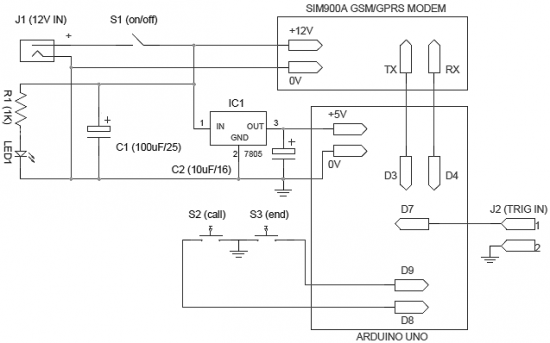
The operation of the system is very simple and self-explanatory. When power is applied to the system, it goes into standby mode. When J2 connector pins are shorted, a pre-programmed warning message is sent to the desired mobile number. You can connect any intrusion detection detector (such as a light guard or motion detector) to the input connector J2. Note that an active-low (L) signal on pin 1 of connector J2 will activate the burglar alarm.
Moreover, an optional “call-alarm” device has been added to the system. It will activate a phone call when the user presses the S2 button (or when another electronic unit initiates an alarm). After pressing the “call” (S2) button, the call can be canceled by pressing another S3 button, the “end” button. This option can be used to generate a “missed call” alarm in the event of an intrusion.
The circuit is very flexible, so it can use any SIM900A modem (and of course the Arduino Uno board). Read the modem documentation carefully before assembling. This will facilitate and make the process of manufacturing the system enjoyable.
List of radio elements
| Designation | Type | Denomination | Quantity | Note | Shop | My notepad |
|---|---|---|---|---|---|---|
| Arduino board | Arduino Uno | 1 | To notepad | |||
| GSM/GPRS modem | SIM900A | 1 | To notepad | |||
| IC1 | Linear Regulator | LM7805 | 1 | To notepad | ||
| C1 | 100uF 25V | 1 | To notepad | |||
| C2 | electrolytic capacitor | 10uF 16V | 1 | To notepad | ||
| R1 | Resistor | 1 kOhm | 1 | To notepad | ||
| LED1 | Light-emitting diode | 1 | To notepad | |||
| S1 | Button | With fixation | 1 |