Heating for two boilers. Two boilers in a boiler room - how to connect - pros and cons. Co-operation of boilers
Installing a solid fuel boiler is the first step to efficiently and economically keeping your home warm. The next steps are to regularly toss up wood or other solid fuels. It is also necessary to maintain the temperature of the heating medium of the heating system within the operating limits at night. And even when the house is visited only on weekends, it is necessary to maintain a minimum temperature in order to avoid moisture condensation on the interior surfaces of the room.
If the presence of condensation is not critical, then when leaving after the weekend, you need to wait for the boiler to stop and drain the water from the heating system in order to prevent the system from freezing. In the case of draining water, all metal elements corrode on contact with air.
It is not necessary to drain the coolant if antifreeze is used instead of water. However, when using antifreeze, due to its high fluidity, high requirements are put forward for thread seals and for shut-off valves.
The most common solution for maintaining the temperature in the heating circuit is the installation of an electric boiler together with a solid fuel one. The minimum amount of additional equipment will allow the electric boiler to automatically take over the heating functions, and the solid fuel one will turn off, without the risk of boiling. Also, the use of an electric boiler eliminates the need to carry out any manipulations with the heating system, leaving the country house until the next weekend. To monitor emergencies and remote control of an electric boiler, there is one that controls the operating mode of heating equipment.
Types of electric boilers
When choosing an electric boiler for installation in addition to a solid fuel one, it is enough to briefly familiarize yourself with the basics of heating water using an electric current, so as not to get caught in the networks of marketers. Electric boilers operate with an efficiency of about 95%. It is not worth checking the veracity of the manufacturer's assurances about the incomparably high efficiency of their devices on your heating system - this can cost extra money, and they will not pay off soon. There are three main types of boilers:
 Heating in them is carried out by an electric heating element (heating element), which is immersed directly into the coolant. In the circuit of such a boiler, both water and antifreeze can circulate. It is unpretentious in operation, but periodically requires replacement of the heating element due to the formation of scale, which reduces heat transfer.
 The coolant in them is water. Heating occurs due to the energy released when an electric current flows through the coolant in the boiler between the electrodes that are inside. It can work without an electric pump in the circuit. Provides smooth heating of water in the system. Over time, as a result of electrolytic reactions, the electrodes dissolve and require replacement.

They heat up any type of coolant by vibrations caused by an induction coil. The temperature from the heating element is evenly distributed over the surface of the flow tank, which almost completely eliminates the possibility of scale formation. For efficient use of the boiler, high-quality control automation is required.
Due to the high price, induction boilers are inferior to heating elements and electrode. Considering the auxiliary function of the electric boiler, the question of the return on investment in advanced technologies fades into the background. The main selection criteria remain: power, quality of materials, device performance, build quality and equipment.
Solid fuel boiler connection diagram
 The most effective connection scheme for solid fuel (TTK) and electric (EK) boilers is parallel. The supply of both boilers to the heating system is carried out at the same point, as well as the return. This scheme excludes inconsistency in the operation of pumps and heat loss in the heat exchanger TTK when the EC is running. The operation algorithm of such a system can be described as follows:
- a working TTK maintains a comfortable air temperature in the room;
- the fuel has burnt out, the coolant cools down, and when the set minimum temperature is reached, the thermostat turns off the pump;
- the air temperature in the room drops below the comfortable one (set by the user) and the EC turns on.
For the system to work properly, it is necessary to take into account some of the features of connecting devices and fittings. The capacity of the TTK pump must be greater than that of the EK pump so that the simultaneous operation of the boilers does not affect the speed of movement of the coolant through the TTK heat exchanger. In the heating system, there must be a non-return valve at the flow of each boiler to prevent counterflow.

To control the operation of the TTK pump, a thermostat is used, which measures the temperature of the coolant at the supply to the check valve. A remote air temperature sensor that controls the activation of the EC should be placed in one of the heated rooms.
To control the EC, they are also used, which allow, using mobile communication, to set the temperature regime for turning on or off the boiler. This method will allow you to program the boiler to turn on only at night to save energy and maximize the benefits of multi-zone tariffing. You can also set the required air temperature, for example, a few hours before arriving at the cottage.
With the right choice of equipment and fittings for the boiler room, the power of two boilers connected according to the proposed scheme will ensure uninterrupted heat supply, creating coziness and comfort in the house. And for owners of country houses - an additional convenience of controlling the heating system.

You just need to add a hydraulic arrow. After that, you can connect in one system any number of boilers (also any) with any number of circuits with any consumers.
However, I made a reservation: in addition to the hydraulic arrow, two more pumps were added - one for each boiler.
How does the circuit with a hydraulic gun and two boilers work?
Boiler pumps supply the coolant from the hydraulic gun to the boilers, where it heats up and goes back to the hydraulic gun. From the hydraulic arrow, the coolant is disassembled by circuit pumps - each takes as much as he needs, without obstacles. If the flow rates through the boilers and through the circuits differ, then part of the coolant will simply fall or rise inside the hydraulic arrow, adding to where there is a lack of it. And the whole system will work stably.
Connection of two boilers: detailed diagram
And, as always, I give a detailed diagram of such a connection:

Reminder. I spoke about this several times, but I will repeat: circulation pumps and check valves, which for each consumer circuit, can be installed not only, as in the diagram, after the supply manifold. But even in front of the return manifold - all three, or partly so, partly so, the main thing is to observe the direction of the flow.
In the diagram above, the pump manifold is assembled from separately purchased parts. And the gidrostrelka, respectively, is also separate. But you can simplify and speed up the assembly of the heating system by using a unit that combines a manifold with a hydraulic arrow.
By including two or more boilers in the heating circuit, one can pursue the goal of not only increasing heating power, but also reducing energy consumption. As already mentioned, the heating system is initially designed to work in the coldest five-day period of the year, the rest of the time the boiler works half-heartedly. Suppose that the energy consumption of your heating system is 55 kW and you are choosing a boiler of this power. The entire boiler capacity will be used only a few days a year; the rest of the time, less power is needed for heating. Modern boilers are usually equipped with two-stage blast burners, which means that both stages of the burner will work only a few days a year, the rest of the time only one stage will work, but its capacity may be too much for the off-season. Therefore, instead of one 55 kW boiler, you can install two boilers, for example, 25 and 30 kW or three boilers: two 20 kW and one 15 kW. Then, on any day of the year, less powerful boilers can operate in the system, and at peak load everything is turned on. If each of the boilers has a two-stage burner, then the setting of the boilers can be much more flexible: boilers can simultaneously operate in the system in different modes of burner operation. And this directly affects the efficiency of the system.
In addition, installing several boilers instead of one solves several more problems. Large-capacity boilers are heavy units that first need to be brought and brought into the room. The use of several small boilers greatly simplifies this task: a small boiler easily goes through doorways and is much lighter than a large one. If suddenly, during the operation of the system, one of the boilers fails (the boilers are extremely reliable, but suddenly this happens), then you can turn it off from the system and calmly start repairing, while the heating system will remain in working mode. The remaining working boiler may not fully warm, but it will not freeze either, in any case, the system will not need to be “drained”.
The inclusion of several boilers in the heating system can be carried out in a parallel scheme and according to the scheme of primary-secondary rings.
When operating in a parallel circuit (Fig. 63) with the automation of one of the boilers turned off, the return water is passed through the idle boiler, which means that it overcomes the hydraulic resistance in the boiler circuit and consumes electricity by the circulation pump. In addition, the return flow (cooled heat carrier), which has passed through the non-operating boiler, is mixed with the supply (heated heat carrier) from the operating boiler. This boiler has to increase the heating of the water in order to compensate for the mixing of the return from the idle boiler. In order to prevent mixing of cold water from a non-working boiler with hot water from an operating boiler, you need to manually close the pipelines with valves or supply them with automation and servo drives.
Rice. 63. Heating scheme of two half rings with increasing power by installing a second boiler
Connecting boilers according to the scheme of primary-secondary rings (Fig. 64) does not provide for such types of automation. When one of the boilers is turned off, the coolant passing through the primary ring simply does not notice the “loss of a soldier”. The hydraulic resistance at the section where the AB boiler is connected is extremely small, so there is no need for the coolant to flow into the boiler circuit and it calmly follows along the primary ring, as if the valves in the disconnected boiler were closed, which in fact are not there. In general, in this scheme, everything happens in exactly the same way as in the scheme for connecting secondary heating rings with the only difference that in this case, not heat consumers, but generators, “sit” on the secondary rings. Practice shows that the inclusion of more than four boilers in the heating system is not economically feasible.
 rice. 64. Schematic diagram of connecting boilers to the heating system on primary-secondary rings
 The firm "Gidromontazh" has developed several typical schemes using hydrocollectors "GidroLogo" for heating systems with two or more boilers (Fig. 65–67).
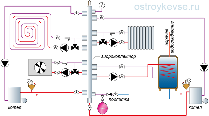 rice. 65. Heating circuit with two primary rings with a common area. Suitable for boiler houses of any capacity with reserve boilers, or for boiler houses of large (over 80 kW) capacity and a small number of consumers.
 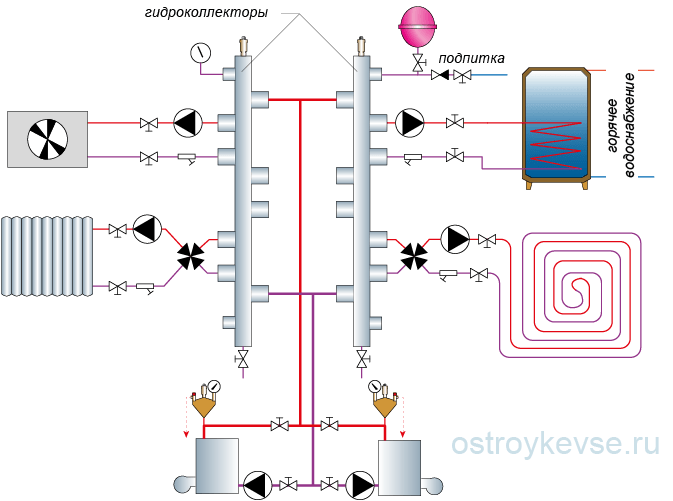 rice. 66. Two-boiler heating circuit with two primary half-rings. Convenient for a large number of consumers with high requirements to the flow temperature. The total power of consumers of the "left" and "right" wing should not differ greatly. Boiler pump capacities should be approximately the same.
 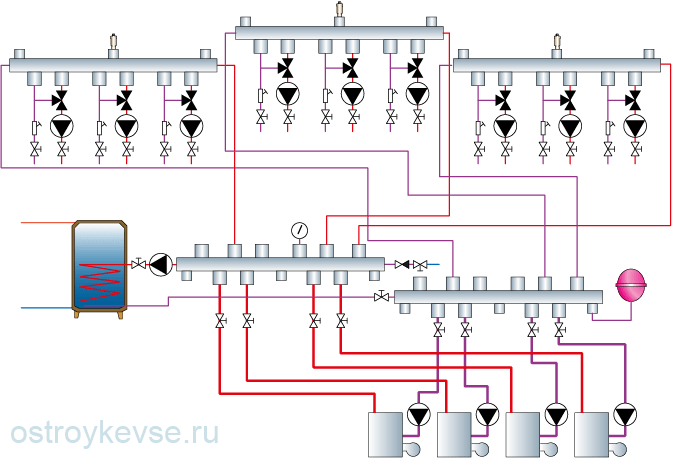 rice. 67. A universal combined heating scheme with any number of boilers and any number of consumers (in the distribution group, conventional collectors or hydrocollectors "HydroLogo" are used, in the secondary rings, horizontal or vertical hydrocollectors are used ("HydroLogo")
 Figure 67 shows a universal scheme for any number of boilers (but no more than four) and an almost unlimited number of consumers. In it, each of the boilers is connected to a distribution group consisting of two conventional collectors or HydroLogo collectors installed in parallel and closed to a hot water boiler. On the collectors, each ring from boiler to boiler has a common section. Small hydrocollectors of the “element-Micro” type with miniature mixing units and circulation pumps are connected to the distribution group. The entire heating scheme, from boilers to element-Micro hydrocollectors, is a conventional classical heating scheme, which forms several (according to the number of hydrocollectors) primary rings. Secondary rings with heat consumers are connected to the primary rings. Each of the rings, located at a higher stage, uses the lower ring as its own boiler and expansion tank, that is, it takes heat from it and discharges waste water. This installation scheme is becoming a common way of arranging "advanced" boiler houses both in small houses and in large facilities with a large number of heating circuits, which allows fine-tuning of each circuit to be fine-tuned.
To make it clearer what the versatility of this scheme is, let's take a closer look at it. What is a conventional collector? By and large, this is a group of tees assembled in one line. For example, in a heating circuit there is one boiler, and the circuit itself is aimed at priority preparation of hot water. This means that hot water, leaving the boiler, goes straight to the boiler, giving off some of the heat to prepare hot water, it returns to the boiler. Let's add another boiler to the diagram, which means that one tee must be installed on the supply and return lines and a second boiler connected to them. But what if there are four of these boilers? And everything is simple, you need to install three additional tees for the supply and return of the first boiler and connect three additional boilers to these tees or not install tees in the circuit, but replace them with collectors with four outlets. So it turned out that we connect all four boilers by supply to one collector, and by return to another. The collectors themselves are connected to the hot water boiler. It turned out a heating ring with a common area on the collectors and boiler connection pipes. Now we can safely turn off or turn on some of the boilers, and the system will continue to function, only the coolant flow rate will change in it.
However, in our heating system, it is necessary to envisage not only the heating of domestic water, but also radiator heating systems and "warm floors". Therefore, for each new heating circuit for supply and return, you need to install a tee and these tees need as many as we have conceived of heating circuits. Why do we need so many tees, isn't it better to replace them with collectors? But we already have two collectors in the system, so we will simply build them up or immediately install collectors with such a number of outlets so that they are enough for connecting boilers and heating circuits. We find collectors with the required number of taps, or assemble them from ready-made parts, or use ready-made hydrocollectors. For further expansion of the system, if required, we can install collectors with a large number of branches and temporarily plug them with ball valves or plugs. The result is a classic collector heating system, in which the supply ends with its own collector, the return flow with its own, and pipes went from each collector to separate heating systems. We close the collectors themselves with a boiler, which, depending on the speed at which the circulation pump is turned on, may have a hard or soft priority or not have such priority, since it turns out to be connected to the circuit in parallel with other heating circuits.
Now it's time to think about the heating system with primary-secondary rings. We close each pair of pipes coming out of the supply and return collectors with an element-Mini hydrocollector (or other hydrocollectors) and we get heating primary rings. Through the pumping and mixing units, we will connect heating rings to these hydrocollectors according to the primary-secondary scheme, those that we consider necessary (radiator, warm floors, convector) and in the amount we need. Please note that in the event of refusals in heat requests even for all secondary heating circuits, the system continues to work because it contains not one primary ring, but several - according to the number of hydrocollectors. In each primary ring, the coolant from the boiler (s) passes through the supply manifold, from there it enters the hydrocollector and returns to the return manifold and to the boiler.
As it turns out, it is not so difficult to make a heating system with at least one boiler, at least with several and with any number of consumers, the main thing is to select the required power of the boiler (boilers) and choose the correct cross-section of the hydrocollectors, but we have already talked about this in sufficient detail.
The most rational heating system is one in which the coolant becomes hot due to the operation of two or three boilers. Moreover, they can be the same in power and type. This rationality is explained by the fact that one heat generator works at full capacity only a few weeks a year. At other times, you need to reduce its performance. And this leads to a drop in its efficiency and an increase in heating costs.
Several combined ones allow more flexible control of the strapping without loss of efficiency, since it is enough to turn off one or two devices. In addition, in the event of a breakdown of one of them, the system continues to raise the temperature in the house.
Types of connection of two or more boilers
The use of more identical boilers requires a special wiring diagram. You can combine them into one system:
- Parallel.
- Cascading or sequentially.
- According to the scheme of primary-secondary rings.
Parallel Features
There are the following features:
- The hot water supply circuits of both boilers are connected to the same line. These circuits must have safety groups and valves. The last can overlap manually or automatically... The second case is possible only when automatics and servos are used.
- join another line. These circuits also have valves that can be controlled by the aforementioned automation.
- The circulation pump is located on the return line in front of the place where the return pipes of the two boilers join.
- Both lines are always connected to hydraulic collectors... There is an expansion tank on one of the manifolds. In this case, a make-up pipe is connected to the end of the pipe to which the tank is connected. Of course, there is a check valve and a shut-off valve at the junction. The first does not allow hot coolant to enter the make-up pipe.
- Branches extend from the collectors to radiators, warm floors,. Each of them is equipped with its own circulation pump and coolant drain valve.
The use of such a piping arrangement without automation is very problematic, since it is necessary to manually close the valves located on the supply and return pipes of one boiler. If this is not done, then the coolant will move through the heat exchanger of the turned off boiler. And it turns out:
- additional hydraulic resistance in the water-heating circuit of the apparatus;
- an increase in the "appetite" of circulation pumps (they also have to overcome this resistance). Correspondingly, energy costs rise;
- heat losses for heating the heat exchanger of the switched off boiler.
Read also: Inverter heating boilers
Therefore, it is necessary to correctly install the automation, which will cut off the switched off device from the heating system.
Cascade connection of boilers
 The cascading boiler concept provides for distribution of heat load among several units, which can work independently and heat the coolant as much as the situation requires.
It is possible to cascade both boilers with staged gas burners and modulating ones. The latter, unlike the former, allow you to smoothly change the heating power. It should be added that if boilers have more than two stages of gas supply regulation, then the third and other stages make their performance less. Therefore, it is better to use units with a modulating burner.
With a cascade connection, the main load falls on one of two or three boilers. Additional two or three devices turn on only when needed.
The features of this connection are as follows:
- The wiring and controllers are designed so that in each unit it is possible to control the circulation of the coolant... This allows you to stop the flow of water in the switched off boilers and avoid heat loss through their heat exchangers or casings.
- Connecting the water supply lines of all boilers to one pipe, and the coolant return lines to the second. In fact, the boilers are connected to the mains in parallel. Thanks to this approach, the coolant at the inlet of each unit has the same temperature. It also avoids the movement of the heated fluid between the disconnected circuits.
The advantage of parallel connection is preheating the heat exchanger before starting the burner... However, this advantage occurs when burners are used which ignite the gas with a delay after the pump is switched on. This heating minimizes the temperature drop in the boiler and avoids the formation of condensation on the walls of the heat exchanger. This applies to a situation where one or two boilers have been turned off for a long time and have had time to cool down. If they have recently turned off, then the movement of the coolant before turning on the burner allows it to absorb the residual heat that has remained in the firebox.
Read also: Heating the house with an air-heating boiler
Boiler piping with cascade connection
Its scheme is as follows:
- 2-3 pairs of pipes from 2-3 boilers.
- Circulation pumps, non-return and shut-off valves. They are on those pipes that are designed to return the coolant to the boiler... The pumps may not be used if the design of the unit includes them.
- Shut-off valves on hot water pipes.
- 2 thick pipes. One is intended for supplying the coolant to the network, the other for returning... They are connected to the corresponding pipes extending from the boiler devices.
- Safety group on the coolant supply line. It consists of a thermometer, a test thermometer sleeve, a manually unlocked thermostat, a pressure gauge, a manually unlocked pressure switch, and a backup plug.
- Hydraulic low pressure separator... Thanks to him, the pumps can create proper circulation of the coolant through the heat exchangers of their boilers, regardless of what the flow rate of the heating system is.
- Heating network circuits with shut-off valves and a pump on each of them.
- Multi-stage cascade controller. Its task is to measure the indicators of the coolant at the outlet of the cascade (temperature sensors are often located in the zone of the safety group). Based on the information received, the controller determines whether it is necessary to turn on / off and how the boilers combined into one cascade scheme should work.

Without connecting such a controller to the piping, the operation of boilers in a cascade is impossible, because they must work as a whole.
Features of the scheme of primary-secondary rings
This scheme provides organization of the primary ring, through which the coolant must constantly circulate. Heating boilers and heating circuits are connected to this ring. Each circuit and each boiler is a secondary ring.
 Another feature of this circuit is the presence of a circulation pump in each ring. The operation of a separate pump creates a certain pressure in the ring in which it is installed. Also, the node has a certain effect on the pressure in the primary ring. So, when it turns on, water comes out of the water supply pipe, falling into the primary circle and changing the hydraulic resistance in it. As a result, a kind of barrier appears on the path of the coolant movement.
Ecology of cognition. Homestead: The most rational heating system is one in which the heating medium becomes hot due to the operation of two or three boilers.
A home heating system based on two boilers is a fairly common solution that saves a lot of money. Usually one of the boilers - the main one - is a gas boiler, convenient to operate, but running on expensive fuel. The second is that a solid fuel boiler is less convenient, requires constant monitoring and periodic fuel supply, but it is more economical (solid fuel - coal, wood - is much cheaper than gas).
When using two boilers, it is rational to combine them into one system and, if necessary, turn on or off an additional boiler. But the operation of these heating devices has a number of differences, which must be taken into account when planning their connection scheme.
Regulation of overpressure in the heating system
The operation of a solid fuel boiler is associated with such a phenomenon as a significant increase in pressure in the system due to an increase in temperature, which is difficult to control. To protect the system in such cases, an open expansion tank is used, connected to the atmosphere, which allows the coolant (water) to expand without increasing the pressure in the pipes. At temperatures exceeding the norm, the excess of heated water simply flows through the hole in the tank into the drain.
An open expansion tank is the main difference between a solid fuel boiler and a gas boiler. The latter is equipped with automation that controls the temperature and pressure in the system, preventing the coolant from overheating. The advantage of such a closed self-regulating system is that a minimum of oxygen gets into it from the outside, reducing the risk of corrosion of metal parts. But even such a system has a certain excess pressure, which is regulated by a safety valve and an expansion tank, only they are mounted in the boiler body itself, and not separately, like in solid fuel boilers.
How to make heating with two boilers
So, there are two boilers that differ in a number of design features. How can you combine them in one system? The most effective option is to divide the system into two independent circuits using a heat exchanger. One of the circuits is open, equipped with a solid fuel boiler; the second - with a gas boiler and radiators. Both circuits are loaded on one heat exchanger.
When planning such a system, it is necessary to take into account the position of all the main and connecting elements so that during operation, maintenance or repair, they can be easily found, inspected, and replaced if necessary. Therefore, before starting the installation, it is better to draw a diagram, apply equipment to it, outline the laying of pipes, mark the installation locations of additional elements.
Requirements for rooms with a solid fuel boiler
Regulatory documents put forward a number of requirements for the rooms in which boilers are installed, depending on the type of boilers. Solid fuel boilers with a capacity of 30 kW or more can be installed only in specially equipped rooms. The boiler room should be located in the center of the rooms that are heated, at the same level or in the basement, which will allow using the generated heat with maximum efficiency, and a minimum of energy will be spent on maintaining circulation. Fuel cannot be stored directly in the boiler room, it is usually stored in an adjacent room. The exceptions are cases when boilers of low power up to 30 kW are used, then the fuel supply can be kept in the boiler room itself in boxes at a distance of at least 1 m from the boiler. Since solid fuel, unlike gas, has to be harvested independently, it is advisable to do this once for the entire heating season, and for this it is necessary to have sufficient storage space, which must be taken into account when choosing a room.
The boiler must not be installed on the floor, but on a foundation or base made of non-combustible materials. The surface of the base or foundation must be strictly horizontal and extend beyond the boiler by 0.1 m at the sides and back and 0.3 m in front. For boilers with a capacity of up to 30 kW, the floor can be made of combustible materials, for example, wood, but then a steel sheet with a thickness of 0.7 mm must be attached around them, which extends beyond the boilers by 0.6 m on all sides. The floor, foundation or base under the boilers must be non-flammable.
The walls, partitions and ceilings of the boiler room must have a fire resistance limit of at least 0.75 hours. When the boiler room is located above the living quarters, its floor, the places where pipes pass through the holes in the floor, door sills, as well as walls at a height of 10 cm must be protected with waterproofing material. A prerequisite for choosing a room for a boiler room is the availability of sufficient natural lighting (at least 0.03 m2 per 1 m3). The height of the boiler room should not be less than 2.5 m. The area of the boiler room must provide access to all elements of the system for the purpose of their inspection or repair. The minimum distance between the boiler and walls (partitions) should be 1 m from the front side and 0.6 m from all others. The minimum volume of the boiler room depends on the power of the boiler used: for a boiler with a capacity of up to 30 kW - 7.5 m3, with a capacity from 30 to 60 kW - 13.5 m3, with a capacity from 60 to 200 kW - 15 m3.
Boiler room ventilation
For normal operation of the boiler, the boiler room must have a ventilation system, not only exhaust, but also supply. An opening with an area of 200 mm2 or more is used as an inlet channel, and a ventilation channel with a section of 14x14 cm is used as an exhaust duct, the entrance of which is located under the ceiling (for boilers up to 30 kW). The area of the inlet of the hood should be the same as the section of the ventilation duct. The hole itself is usually covered with a lattice. Both the supply and exhaust ducts should not have any dampers - they should always be open and preferably clean. When using more powerful boilers (from 30 kW and above), the ventilation holes must have a cross section of at least 20x20 cm and at least half of the chimney cross section.
It is best to make the opening of the supply duct behind the boiler; its height above the floor level should not be less than 1 m. An air duct of the same section can also be used as an inlet duct. When using an air duct, a damper that regulates the air flow is allowed, but it should not block the duct by more than 80%.
All ventilation ducts are made of non-combustible materials. A forced exhaust ventilation system must not be installed if the chimney is naturally draft.
Sewerage
To drain excess water when it overheats, the boiler room must be equipped with a sewerage system connected to the sewerage system of the house by a floor ladder. If for some reason this cannot be done, a well with a hand pump is equipped in the boiler room. When overheated, water will accumulate in it, and pump it out with the help of a pump. To supply water to the boiler, the system is equipped with an intake valve, in front of which a check valve is usually also mounted. The boiler is connected to the cold water system with a flexible hose.
Requirements for rooms with gas boilers
Now let's consider the requirements that are put forward for rooms with gas boilers. Gas boilers, the power of which does not exceed 30 kW, can be installed on any of the floors in almost all rooms, except for those in which people are constantly present (bedrooms, living rooms, children's rooms, as well as garages and stairwells if the boilers are equipped with an open combustion chamber) ... When using liquefied gases, there are more restrictions, for example, they cannot be installed in basements or basements. Boilers with a capacity exceeding 30 kW are installed in separate rooms with a ceiling height of at least 2.5 m. The volume of the room for gas boilers with a capacity of up to 30 kW should be at least 7.5 m3 if the boiler is in the kitchen, where there is also and a gas stove for 4 burners, the minimum volume of such a kitchen is 15 m3.
Ventilation of the room with a gas boiler
To provide air supply to a room with a gas boiler, an inlet opening with a cross section of at least 200 cm2, located at a height of no more than 30 cm from the floor, is used. Air can come both from the street and from neighboring rooms.
In boiler rooms where boilers operating on liquefied gas are installed, the exhaust outlet must be at the bottom, at floor level, and the exhaust duct must slope outward. This is due to the fact that liquefied gas is heavier than air, and if it leaks, it will go down. The inlet must also be at floor level and have a section of 200 cm2.
Construction materials and heating systems
The floor under the gas boiler must be made of non-combustible materials or covered with steel sheet or other non-combustible material, extending beyond the boiler by 0.5 m. The same applies to the walls if the boiler is attached to them.
Gas pipelines are made of seamless steel pipes or longitudinal electric welded pipes. It is also possible to use copper pipes, the wall thickness of which is not less than 1 mm, indoors.
In a heating system, copper or plastic pipes are usually used for heat carriers. When using plastic pipes in places where the temperature is high enough, for example, near a boiler, their sections should be replaced with copper or steel pipes. Copper pipes are sensitive to mechanical damage, therefore, when using them, filters must be installed that do not allow small particles to enter the system. Inside copper pipes, the walls are covered with a protective layer of copper oxide, and solid particles can damage it.
When installing copper pipes, their edges must be carefully sanded so that there are no sharp edges, and wrapped inward. Uneven edges can cause turbulence in the system, noise, bacteria build-up and damage to the pipe cover. Copper pipes must be correctly selected in diameter - too thin pipes with a high water pressure can quickly fail due to a protective layer damaged by a strong pressure. In addition, thin pipes increase the load on the pump and impair the boiler burner performance. And one more nuance regarding copper pipes. When using pipes with a diameter of less than 28 mm, it is undesirable to connect them by soldering, since high temperatures affect their structure, significantly reducing their strength and resistance to oxygen.