The program to optimize the cutting of plate materials. Using business waste. Various types of letters

Cutting - a program for cutting sheet materials: wood chipboard, glass, etc. The DSP cutting program makes it possible to reduce and optimize the consumption of the material, it makes accounting for waste, including "business", which are not taken into account when calculating the order value. The utility can be used in enterprises engaged in the mass production of cabinet furniture, for this in its functionality, the concept of order has been introduced. All executed orders are automatically recorded in the order base, subsequently it is possible to repeat or change them. Download free Cutting You can on this site.
To start working with the utility, you need to set the size of the sheet and parts that will be cut out of it. Next, the program will independently select the optimal version of the cutting with the lowest amount of waste. If necessary, you can use the database of materials available in the program, in which the standard dimensions of sheets or rolls are laid. In this case, it is enough to specify the material for cutting, and the utility will automatically make a calculation according to the standard sheet parameters.
The program for cutting works on two basic algorithms for optimizing the DSC flow rate - a decrease in overall waste and an increase in continuous cropping. A decrease in overall waste involves cutting with a minimum amount of cropping. The mode of increasing continuous trimming, in addition to reducing waste, is used to create maximum trimming, which can then be used for another order. You can also save on the material by combining two orders if the same material is used for them.
The main advantages of the utility cutting
- Two cutting optimization algorithm.
- Database of standard sheet size.
- Work with two types of edges.
- Work with both sheets and rolls.
- Database of completed orders.
During the cutting, all the cuts are produced from one edge of the sheet to another - either horizontally, or vertically. The material consumed on the cut and other technological operations is taken into account when calculating the cutting. The utility allows you to work with two variety of edges. The program allows you to optimize the consumption of not only sheets, but also rolls. If necessary, it is possible to use the cutting in the network mode.
At first I used the Cutting 2 program, then Cutting 3. They differ quite strongly. But the version of Cutting 2 I liked more. In the third version there are additional possibilities that, by and large, not very much and are needed for small production. Cutting 2 and now helps me in the preliminary calculation of the amount of material and the length of the cut line for large orders, such as the kitchen. To create a final cutting card, I use the NOWY ROZKRój (Cut Optimiser or New Cut Manager) program from the creators of the PRO100 program. . Both sites can be switched to Russian and familiarize yourself with the description of the programs. And now I will describe the uncomplicated process of creating carding cards. .
Open any project created by us in Pro100. Click on the σ tab.
The table opened will reflect the table in which all project elements will be indicated with their characteristics. At the bottom of the window we find the Copy All tab.

Click on it. Now we can insert a table with our elements in the list of parts in Cutting 2. But we need only elements of the main material, let's say the chipboard thickness18 mm. Therefore, open Excel and insert the list of Pro100 elements. Now we allocate those lines in which the elements are not 16 mmi remove them. As a result, there remains a table consisting of 4 columns, in one of which in all cells only number 18. We allocate and delete this column. The remaining items allocate and copy. Run the Cutting program 2. Details table on the right.

If it is not empty, click on the x icon over the right table and confirm the cleaning of the list. Now click on the right key on the first empty list of the list and in the drop-down menu, select the line to add from the clipboard.

Click on the execution icon.

Card cutting ready. You can print and use. But I ran into some inconveniences. For example, numbers are small, the cut line is not clear enough.

People who cried material for me were unhappy with the need to use magnifying glass. But for the preliminary calculation of the cost of the product, the program approached ideally due to the above-described part of parts from Pro100 in Cutting 2.
NOWY ROZKROJ program is a better optimizer.

But all the dimensions of the parts must be administered manually.

The program calculates several cutting options at once.

Depending on what is important to you, you choose your own option. It is more suitable for me with a smaller total long cut line, and someone needs a variant with a smaller number of cropping (trash).
First, in the settings, I specify the option of cutting without a strip,

which allows you to place a greater number of details. After the first attempt at cutting, I see, a lot of free space remains on the last sheet. If more than 30% are not occupied by the details, then in the program parameters, I specify the version of the horizontal

and launch the final calculation. The remaining horizontal bandwidth of the material of the material seller leaves itself, which reduces the cost of furniture. Calling cards created by Nowy Rozkroj program are sufficiently detailed and distinct, dimensions are displayed perfectly.

The result of cutting can be different. For example, you made the optimal cut when an option without a strip, and you have 3 sheets and 3 details. This is especially important if this color of the material seller does not sell the stripe, but only a sheet. In this case, apply the following option:
When adding each part, remove the mark in the table properties table on the structure position.

Then, looking at your project, go through the detail and mark the structure in detail, the structure on which can only be aware of the design, i.e. Other structural options on these parts are not acceptable. If this method does not help, then reduce the size of hidden parts, such as grounds and connecting strips, 10, or more, mm. But do not overdo it.
There is another important plus from this program. If you marked the edge on any side of the part, then it will not eat from this side to another when you turn the part with the optimizer, which can happen in other programs. In the event that the end edge is paper, the dimensions of the parts remain the same as in the project, and if the PVC edge is 1-2 mm thick, then do not forget to take away from the size of the adjacent side with the edge thickness of the edge.
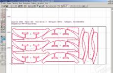
Example of cutting cards
At the beginning of the roller, until the start of the program of Nowy Rozkró, do not pay attention. And then all on the topic. A small technical hitch.
If your sheet, for example, 2800 at 2070, and trimming on the side of 10 mm, forgetting that 4 mm is needed on the cutting, you specify the size of the part 2790 to 600 with the edge of 2790. As a result, the edge slides on 600. Please note This is attention. I once did not check the card and gave it to work. First, the guys suffered when the edge was glued to the side 600, because The detail rested in the door of the workshop, had to move the machine. No one thought that the distance from the machine to the wall 2.5 m may be ever sufficient. And secondly, I had to pay for me to shove the edge along the long side, and at that moment I did not count on it. Therefore, be careful.
The error with which you may encounter when drawing up carding cards
The program is designed for a comprehensive solution to the task of cutting sheet materials. It combines the possibility of a system for training management programs with the functions of organizing the production process. The approach to the solution used in the program summarizes the experience of a number of enterprises operating thermal cutting machines.
Using a database
The program combines traditional technician processing tools with a database. The database is assigned not only to the task of managing various data, but also the management of the system of the system as a whole, since the database objects are and sheet cutting programs. First of all, parts that can be imported from another system are entered into the database, are built by technologist or macros-based.
Creating Macro Based Parts
In the course of working with the program in the conditions of production, a number of typical parts are gradually allocated, characterized by the sizes and the presence or absence of some auxiliary elements. Such standard details are conveniently stored in the library in a parameterized form and use when creating real parts by specifying the actual values \u200b\u200bof the parameters. The program allows you to use the parameterized parts when creating a part in the database. Entering part parameters is carried out in the dialog box. Users have the ability to develop macros that describe geometry and, if necessary, processing typical parts. It is also possible to specify a description of the parameters to configure the dialog box and control the input data.

Correction of not correct geometry when importing DXF files.
The system implements the ability to configure the accuracy of contour coupler when importing DXF files. The accuracy of the conjugation is the distance, within which the incomprehension of the initial segments, eliminated when converting them into the contours, is permissible. The accuracy of the pairing has an impact on whether they will be combined into one contour close segments or not. If the boundary points of the segments do not coincide, but the distance between them is within the accuracy of the conjugation, such segments are interconnected (combined into a single circuit). Segments are conjugated due to their continuation, truncation or displacement of endpoints - depending on the mutual location of the segments:
a) truncation of segments.
b) extension of segments.
c) the displacement of the "short" segments segments (having a length of less than the accuracy of the pairing) are eliminated.
After removing the "short" segment, the adjacent segments are pairing. Segments (or parts of segments), which are superimposed on each other within the accuracy of the pairing, are combined. Details are conveniently viewed simultaneously with the list of all the details. To manage details and other database objects, a single visual mechanism that uses two panels is proposed. This approach allows you to perform actions on database objects from the list (creating, deleting, editing and viewing parameters) and at the same time see on the adjacent panel graphic representation of the list of list (parts, sheets, sheets, sheets, etc.). In addition, the presence of two panels makes it convenient to work with objects, including other objects in turn. So, for example, the cutting sheet contains parts. To organize view details related to different sheets of sheets, in one panel you can display a list of sheets of sheets, and to another - a list of parts placed on a specific sheet.

Task on cutting
The program organizes the interaction of various objects involved in the process of cutting sheet material. From the details that you need to make, a reference set is formed. Then in the opening on the cutting sheets are included for the manufacture of parts. The program provides the ability to automatically and manually locate the details of the opening on sheets. At the same time, the program tracks the number of unstoppable parts and the ability to manufacture parts from the selected sheet.
Automatic placement of parts on sheet
In automatic placement mode, the program lays the details of the sheets on the sheets in an optimal way. Required additional sheets can be automatically taken from the warehouse. The program also allows you to automatically place selected parts on a specific sheet. At the same time, the set distances to the edge of the sheet are maintained and between the items. Automatic accommodation strategy provides a very high material use ratio. The user has the ability to choose the optimal ratio between the quality of the placement of parts and the calculation time. With automatic placement, the method of sealing parts on a sheet filled not entirely. This affects the form and proportions of business waste, taking into account the specifics of its further use. Managing the selection of parts for filling holes allows you to use smaller or larger parts in the emptiness inside parts or larger parts or not to fill the holes.

Manual placement of parts on a sheet
It is provided for manual mode of placement of parts on a sheet. In this mode, the part is selected from the list of unimpressible details of the job on the cutting and placed onto the sheet, and then moves to free space by the graphics editor. There are also means of precise control of the mutual location of objects. The combination of automatic and manual placement of parts makes it possible to benefit from the benefits of each mode for the most efficient operation.
Control of movement of parts
In manual placement mode, the program assumes a number of useful functions. These include various ways of moving parts in compliance with the required distances between the parts and between the parts and edges of the sheet, as well as the ability to place parts close to each other.
Strict control of movement of parts.The inclusion of this feature allows you to move the parts on the sheet on the monitor screen, as real objects for which other parts and the edge of the sheet are an irresistible obstacle.
Warning control of the movement of parts. With warning control, the movement of parts is not limited to the free sheet area. However, if you get into the overlap area with other objects, it is diagnosed with an invalid location by changing the color of the moved part.
Move the details until it stops. This feature makes it possible to press the part close to the very edge of the free area of \u200b\u200bthe sheet. In other words, with this operation, the part is moving in a certain direction until it is represented into the part or the edge of the sheet.
Copying parts close to each other.
When copying parts in this mode, the distance is automatically determined to which the part can be moved in the specified direction so that the parts are located close to each other.
Combining parties to parts Allows you to orient the details in such a way as to combine them with the selected parties.
Leveling parts in a straight line. This feature is useful when the details are proceed with through the cut.
Processing programming
After the parts are placed on the sheet, processing is programmed. In the simplest case, it is enough to specify the processed contours of the parts. The program builds the trajectory of the tool movement, taking into account the necessary amendments, forms approaches, waste and auxiliary movements of the instrument, turning on and off the cutter, feed, correction, etc.
Approach and waste.It is possible to provide a variety of ways to approach the approach to the processed contour (in a straight line, on the arc, on the normal, by tangential, etc.), selecting the approach (automatically or explicitly) and the mode of operation of the cutter at various stages of processing.
Jumpers. At the contour of the part can be isolated unrealized areas - jumpers. When building a trajectory, the program automatically generates in such places to enable and turn off the cutter and embeds the sections of the approach and waste.
Bridges Between the details allow you to handle several parts without turning off the cutter. The task of the transition points of the trajectory from one detail to the other is made after the placement of parts and is taken into account when building the final cutter trajectory.
Loop Provide high-quality handling of parts of parts and can be assigned for any angle.
Assigned processing. To simplify operation, the processing of parts can be programmed at the preliminary step so as not to repeat the same steps to repeatedly turn on the elements in the cutting.
Manual processingyu. For non-standard cases, it is possible to build a trajectory and tasks of technological commands explicitly.
Subrogram Provide the structuring of the received control program and allow you to reduce the volume of the formed text.
Processing details of the combined cut. Pair of parts, placed on a sheet at the distance of the width of the cut, can be processed by a single cut off the cutter. When processing individual parts, it is enough to specify the outline of the part that will be processed first.
Preliminary punching.When processing the sheets of high thickness, you may need to first break the hole in the sheet, and then perform the main processing. For such pre-processing, the sheet can be used either a separate cutter or drill. The program allows you to process with a preliminary breaking hole. It is possible to specify various methods of preliminary punching.
Positioning over the material. In some cases, it is necessary when switching from contour to the contour to move the cutter, bypassing the details and wastes separated from the sheet. This feature is necessary when cutting the foam rubber. Sometimes it is required with thermal cutting to prevent collision cutter with cut parts and waste. The program provides the possibility of such a positioning, taking into account the predetermined distance to the part and to the edge of the sheet.
Automatic processing
Automatic processing mode makes it possible to maximally simplify the programming of the processing of a large number of parts. The program itself assigns the detail sequence on the sheet and performs processing. Different parts bypass details ensure compliance with the necessary processing conditions.

Cutting edges for welding
The cutting edges for welding can be performed on thermal cutting machines equipped with three-core blocks. The program provides for the possibility of processing parts both with constant and variable chamfer. The permanent chamfer is characterized by constant facial and rear corners and heights along the entire length. The chamfer variable is characterized by a uniform change in angle and height in length. The program automatically embeds in the trajectory of the movement of the cutter Special sections - windows of the climb in the places of inclusion of lateral cutters and reversal loops, which provide the correct orientation of side cutters and comply with the necessary processing conditions. The position of the windows windows can be changed using a graphic editor.

Marking sheet
Application of marking on the sheet can be done with a powder or core. Markup contours can be stored in the database along with the part. In this case, the markup turns out to be placed on the sheet along with the details. To program the work of the markup block, it is enough to specify the markup contours in the desired sequence. The program will produce all the necessary shifts and build a trajectory.
Multi-contact treatment
On machines equipped with several calipers, several parts can be cut out at the same time. The program provides automatic and manual placement of parts, taking into account the possibilities of such equipment. When programming processing, the required layout of the calipers is performed automatically.
Using business waste
From the unused part of the sheet, a business waste is formed, which can be placed in a database for subsequent use.
Documenting
The program forms the following output documents:
- card cutting sheet
- specification of cutting sheet
- specification of task on cutting.
 As a rule, the specific type of output documents is determined by the traditions of the enterprise. The report generator included in the technologist has a flexible mechanism for setting up the format of documents and the amount of information displayed.
Automatic generation of text
In the process of building geometric objects and design, the cutting of the sheet is forming the text of the program in the technologist. The program includes the entire sequence of action produced and can be used for further work. This allows you to flexibly combine the convenience of the dialogue mode with the advantages of a text presentation of the program to which:
- Use of previously written programs and macros, quickly modifying them
- Parametrization for typical parts
- Using conditional operators, cycles, arithmetic expressions and functions
- The ability to debug and correct errors
Means of development and debugging programs
The system includes a set of tools for working with the program in Technol:
Commands execution (Run the operator, go to the macro, execute the program to the end to the cursor, etc.) allow you to perform and debug the program on the technologist. Using these commands, you can execute the program entirely or in parts, suspending the process for analyzing the results of the execution of individual operators.
Means of control It is possible to view variable values, use a graphic window for visual control of the program objects and view diagnostic information formed during the program execution.
Getting a control program
The postprocessor, which is part of the technologist, allows you to form control programs for various CNC machines on the product processing program and hardware data included in the system. Using the machine processing program obtained for a single machine, you can get UE for any other machine from the equipment list.

Configuring specific equipment with CNC
Tehtran provides the ability to configure specific equipment with CNC. To describe the equipment, you need to fill the passport of the machine and create a machine module in a special language technician. Such a mechanism allows users to independently take into account the features of the formation of the UE, developing their own modules based on existing one.
Version 2 functionality:
The automatic placement mode with a homograph allows:
- Place parts on sheets and businesswasters of arbitrary shape
- Additionally place parts on sheets on which parts are already placed by increasing the material utilization factor
Treatment checking
- Control of cutting parts when processing
- Tracking the output of the processing trajectory outside the sheet
- Checking the presence of untreated parts
Advanced mechanism for automatic formation of business waste contours
Increase the number of contours in the formation of business waste in automatic mode
Association of related fragments of sheets of business waste
 |
Batch processing
Batch processing is implemented - the mode of operation in which a number of action is automatically performed above the sheets of sheets. The packet processing task is to perform a sequence of long operations, save the user from the multiple opening of the database objects, thereby reduce the amount of routine work and improve efficiency.
In packet processing mode, the following actions can be performed:
- checking the correct location of parts on the sheet
- automatic processing of details
- check the resulting trajectory for slashes
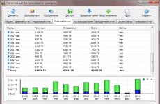
- getting Contours of Business Department, Card Calling, Managing Programs, Processing Statistics, Specifications Staying sheets
- export details and trajectories
Calculation of the cost of cutting parts
Calculation allows you to determine the cost of work during the reporting period. The report forms the cost of cutting, calculated based on the user-filled special tables. Calculation formulas can be adapted. In assessing the value of the decision takes into account:
- the cost of the detailed sheets;
- the cost of business waste;
- the cost of scrap;
- slag value;
- cost, calculated based on:
- total processing time (includes damping equipment and staff salary);
- the number of pores (includes the consumption of nozzles, gases, energy);
- the path / time of cutting (includes the consumption of nozzles, gases, energy).
- the path / time of idle moves (turns on the consumption of gases, energy).
The cost is calculated separately for each sheet cutting.
Costs can be summed up for the opening specification.
The cost can be distributed in detail in proportion to their area and perimeter.


Calculation formulas can be adapted individually for specific requirements of the enterprise.
Library elements of air ducts
A library of air duct elements consisting of the shaped parts of the air ducts (optional is optional).
|
|

Using the library allows you to:
- get sweated parts with the required characteristics
- using the preview window, select the optimal combination of those parameters that are not fixed (for example, the location of the cut line of the cylindrical section).
- include additional connecting elements in the part - folders.
- take into account the thickness of the sheet to compensate for the deformation of its outer and inner surfaces arising during the flexible process.
- if necessary, split the item into several fragments
- select elements and assign geometric and technological parameters in dialog
- automatically form an explosion taking into account the radius of the gib
- promptly view and change destroy
- view three-dimensional models of obtained joints
Application of the library of air duct elements will allow:
- reduce designer design time
- consider technological features of the element connections
- get high accuracy to build raw
- control the geometry of the built plot at the design stage
Import DSTV files (NC)
Import will allow you to transfer not only the geometry of the details and its designation, but also required for cutting the number of parts with a material thickness indicating the thickness of the material. Programs Supporting DSTV format (NC) - Tekla Structures, Advance Steel, Strucad.
 |


It is possible to cut the sheet material and manually, but it takes a lot of time and special skills. It is much easier to do this by using related programs. They will help optimize the cutting card, will offer other options for location and allow it to edit it yourself. In this article, we picked up for you several representatives who perfectly cope with their task.
Astra cut out allows you to work with orders, importing their billets from the catalog. In the trial version of the templates, only a few, but their list will expand after the license is purchased. The user manually generates a sheet and adds items to the project, after which the software automatically creates an optimized cutting card. It opens in the editor, where it is available for change.

Astra S-Nesting
The following representative differs from the previous one that offers only the main set of functions and tools. In addition, you can add only pre-prepared details of certain formats. The cutting card will appear only after purchasing the full version of Astra S-Nesting. In addition, there are several types of reports that are formed automatically and can immediately be printed.

Plaz5
Plaz5 is obsolete software, no longer supported by the developer, but this does not prevent him from qualitatively perform his task. The program is quite easy to use, does not require any special knowledge or skills. The cutting card is created quickly enough, and from the user you only need to specify the parameters of parts, sheets and make the design of the card.

Orion.
The last on our list will be ORION. The program is implemented as multiple tables in which the necessary information is entered, and after the optimized cutting card is created. Of the additional functions, only the ability to add an edge is present. Orion is distributed for a fee, and the trial version is available for download on the official website of the developers.

Cutting sheet material is a rather complicated and time consuming process, but this is if not to use a special software. Thanks to the programs that we have reviewed in this article, the process of drawing up the formation card will not take much time, and the user needs to make a minimum amount of effort.
Carding card - is a documentation that displays which parts should be cut from the chipboard. But, in fact, you can not only cut the chipboard, but also any sheet material.
With the help of cutting, you can view how you can decompose the parts on the sheet. The map also has information about the remains that will be as a result of cutting.
As a result, the advantage of cutting is to display the amount of material that will be required to create furniture.
You can make a cutting chipboard in the firm where you will buy materials, but our task is to create cabinet furniture at home with minimizing costs, and it is not possible to make it possible, even a newbie.
To create a map, we will use the Cutting 2 program (Cattle). You can download it at the end of the lesson.
The program interface looks like this:
In the field of "Materials", you need to set the parameters of the chipboard sheet or if you have remnants that plan to cut out, then the size of the residues. As for the size of the chipboard, I use the SWISSPAN manufacturer's sheets, the dimensions of which are 2750 * 1830 mm (for large sheets) and 2440 * 1830 mm (for small).
Also note that in the settings of the chipboard sheet it is necessary to set the values \u200b\u200bof the "drew sheet", since the sheets initially have chips.


If you plan to glue the edge of PVC, or you want to calculate how much paper edges will be needed for a sizing, then you can also set it in the "properties".

For convenience, it is possible to select the edge color. This opportunity will facilitate the work when using more than 1 type of edge. For example: 2mm and 0.6 mm or use several colors.
After adjusting all parts, press the "Cut" or F9 button.

We see that the cut turned out unsuccessfully. To solve the task, you can try to cut out again or shifting the details yourself. By clicking on the item and dragging to the right place. There is also an option to decompose everything, dragging into the details in "not placed" and independently put as needed.

Important! When drawing up the cutting, follow yourself, so that there is a place for feeding, as you can do everything "optimally" with a line with a snake. After that no one wants to cut them.