GOST for electrical outlets. Conventional designation of sockets and switches in the drawings. Aging resistance, water ingress protection and moisture resistance
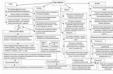
Planning the placement of electrical wiring in a room is a serious task, the accuracy and correctness of which depends on the quality of its subsequent installation and the level of safety of people in this area. In order for the wiring to be placed efficiently and competently, it is required to draw up a detailed plan in advance.
It is a drawing made in accordance with the selected scale, in accordance with the layout of the housing, reflecting the location of all electrical wiring nodes and its main elements, such as distribution groups and a single-line schematic diagram. Only after the drawing has been drawn up can we talk about connecting an electrician.
However, it is important not only to have such a drawing at your disposal, you also need to be able to read it. Each person dealing with work involving the need for electrical installation must navigate in the conventional images on the diagram, denoting various elements of electrical equipment. They look like certain symbols and they are contained in almost every electrical circuit.
But today we will not talk about how to draw a plan diagram, but about what is displayed on it. I will say straight away complex elements such as resistors, automatic machines, circuit breakers, switches, relays, motors, etc. we will not consider, but consider only those elements that are encountered by any person every day, i.e. designation of sockets and switches in the drawings. I think it will be interesting for everyone.
What documents regulate the designation
GOSTs, developed back in Soviet times, clearly define the correspondence of the elements of the electrical circuit to certain established graphic symbols on the diagram and in the design documentation. This is necessary to maintain generally accepted records of electrical system design information.
The role of graphic symbols is performed by elementary geometric shapes: squares, circles, rectangles, points and lines. In various standard combinations, these elements reflect all the components of electrical appliances, machines and mechanisms used in modern electrical engineering, as well as the principles of their control.
Often a natural question arises about the normative document governing all of the above principles. Methods for constructing conventional graphic images of electrical wiring and equipment on the corresponding diagrams is determined by GOST 21.614-88 "Conventional graphic images of electrical equipment and wiring on plans." From it you can learn how sockets and switches are indicated on electrical diagrams.
Designation of sockets in the diagram
Regulatory technical documentation gives a specific designation of the outlet on electrical diagrams. Its general schematic view is a semicircle, from the convex part of which a line extends upward, its appearance determines the type of outlet. One feature is a two-pole socket, two are a double two-pole, three fan-shaped is a three-pole socket.
Such sockets are characterized by a degree of protection in the range IP20 - IP23. The presence of grounding is indicated on the diagrams by a flat line parallel to the center of half of the circle, which distinguishes the designations of all sockets of open installations.

In the event that the installation is hidden, the schematic images of the outlets are changed by adding another feature in the central part of the semicircle. It has a direction from the center to the line indicating the number of poles of the socket.

At the same time, the sockets themselves are embedded in the wall, the level of their protection against moisture and dust is in the range given above (IP20 - IP23). The wall does not become dangerous from this, since all parts that conduct current are reliably hidden in it.


In some diagrams, the outlet designations look like a black semicircle. These are moisture resistant sockets, the degree of protection of the shell is IP 44 - IP55. Their external installation on the surfaces of buildings facing the street is allowed. In residential areas, such outlets are installed in damp and damp areas, such as bathrooms and showers.

Designation of switches on electrical diagrams
All types of switches are schematic in the form of a circle with a line at the top. A circle with a dash containing a hook at the end stands for one-button light switch for on-site lighting(degree of protection IP20 - IP23). Two hooks at the end of the line represent a two-button switch, three - a three-button switch.


If a perpendicular line is placed above the dash on the schematic designation of the circuit breaker, we are talking about flush-mounted switch(degree of protection IP20 - IP23). Line one - single-pole switch, two - two-pole, three - three-pole.

The black circle denotes a moisture-resistant open-circuit switch (degree of protection IP44 - IP55).
The circle intersected by a line with dashes at the ends is used to represent on-line switches (switches) with two positions (IP20 - IP23) on electrical diagrams. The image of a single-pole switch resembles a mirror image of two conventional ones. Waterproof switches (IP44 - IP55) are marked with a filled circle in the diagrams.

As indicated by the switch box with socket
To save space and for the purpose of layout, an outlet with a switch or several sockets and a switch are installed in a common unit. Probably, many of these blocks have met. Such an arrangement of switching devices is very convenient, since it is located in one place, besides, when installing electrical wiring, you can save on strobes (wires to the switch and sockets are laid in one strobe).
In general, the layout of the blocks can be any and everything, as they say, depends on your imagination. You can install a switch box with socket, multiple switches, or multiple outlets. In this article, I simply have no right not to consider such blocks.
So, the first one is a block socket switch. Designation for flush-mounted installation.

The second, more complex unit, consists of a one-button switch, a two-button switch, and an earthed socket.

The last designation of sockets and switches in electrical diagrams is shown as a block of two switches and a socket.

For clarity, only one small example is presented; you can assemble (draw) any combination. Once again, it all depends on your imagination).
page 1

page 2

p. 3

page 4

p. 5

page 6

page 7

page 8

page 9

p. 10

page 11

p. 12
1 area of use
State the section in a new edition:
This standard applies to stationary sockets with interlocked switches (hereinafter referred to as sockets with switches), an earthing contact and without it for household and similar purposes, intended for connecting electrical receivers with a rated voltage of St. 50 to 440 V and rated currents not exceeding 32 A to an alternating current electrical network for indoor and outdoor installation in buildings.
Sockets with switches that comply with this standard are manufactured as a combination of socket (s) in accordance with GOST R 51322.1 and a switch in accordance with GOST R 51324.1 and / or GOST R 51324.2, which are supplied as assembly units.
When using fixed sockets with screwless terminals switches, the rated current is limited to 16 A.
This standard does not apply to the requirements for flush-mounted back boxes.
The standard covers the requirements for open mounting boxes required for testing outlets.
Notes (edit)
1 General requirements for junction boxes - in accordance with GOST R 50827.
2 This standard does not apply to sockets with interlocked switches in combination with devices according to GOST R 50345, GOST R 51326.1 and GOST R 51327.1. The standard can be used as a guide to the test requirements for these additional devices, if necessary.
This standard does not apply to:
Sockets with switches for industrial use;
Safety extra-low voltage sockets with switches.
Sockets with switches that comply with this standard are designed to operate at ambient temperatures up to 25 ° C with an allowable temporary increase up to 35 ° C.
The standard should be used in conjunction with GOST R 51322.1.
Test methods are in italics throughout the text of the standard.
Supplements that take into account the needs of the country's economy are given in Appendix A.
2 Normative references
5 General test requirements
7 Classification
Reversible,
Keyboards,
Push-button,
Powered by a cord,
Micro-gap,
Optical,
Acoustic,
Other inclusion mechanisms;
7.2.101.2 depending on the connection method:
Single pole,
Bipolar,
Three-pole,
Three-pole with neutral included;
7.2.101.3 by type of blocking:
Mechanical,
Electric,
Electronic,
Combined of the above;
7.2.101.4 by the presence of a fixing device:
Without fixation,
With fixation.
8 Marking
10 Protection against electric shock
10.102 Metal parts of the circuit-breaker mechanism, such as an axle or suspension pivot or balancer, not isolated from live parts, shall not protrude from the enclosure.
Compliance is checked by inspection, if necessary after dismantling the part that actuates the switch.
NOTE If the operating part of the circuit-breaker fails, verification is carried out after the test of clause 28.
10.103 Metal parts of the switch mechanism, such as the axle or suspension pivot or balancer, shall not remain exposed after the switch is in the service position.
They must be insulated from exposed metal parts, such as the metal frame holding the flush-mounted switch base, to be installed in metal boxes, and from the screws holding the switch base to the supporting surface.
Additional requirements do not apply if the metal parts of the mechanism are separated from live parts so that the creepage distances and air gaps are at least twice the values specified in 27.1, or if the sockets with switches are provided with earthing clamps reliably connected to earth.
Compliance is checked by inspection and, if necessary, by measurement and by the tests of clauses 17 and 20.
11 Grounding
12 Terminal clamps
13 Fixed socket design
13.102 Handles of rotary switches shall be securely connected to the shaft or other part that drives the mechanism.
Compliance is checked by the following test.
An axial tensile force of 100 N is applied to the handle for 1 min. After that, the handles, which have only a working direction, are turned, if possible, without unnecessary effort 100 times in the opposite direction.
The handle must not be removed during the test.
13.103 The drive of the switch, after operation, must automatically take a position corresponding to the position of the moving contacts, with the exception of pull-cord and one-button switches, in which the drive must take a single position.
13.104 Switches shall be of such a design that the movable contacts should be only in the "On" position. and "Off".
An intermediate position for these contacts can only be provided if the drive part also has an intermediate position and there is reliable insulation between the movable and fixed contacts.
If necessary, the insulation between the fixed and moving contacts in the intermediate position can be tested for electric strength by applying to the appropriate terminals, without removing the cover or cover of the switch, for 1 min a test voltage of an almost sinusoidal shape with a frequency of 50 or 60 Hz, a value of 1250 V for sockets with rated voltage up to 130 V incl. or 2000 V - for sockets with a rated voltage of St. 130 B.
Compliance with the requirements of 13.103 and 13.104 is carried out by inspection, by test installation and, for switches with intermediate positions, by the above electrical test.
13.105 Circuit breakers intended for alternating current only shall be of such a design that would exclude the occurrence of arcing when the circuit breaker actuator is operated slowly.
Compliance is checked by the following test, carried out after the test of clause 21. Using the switch, switch off the circuit 10 times in succession, while slowly moving the actuator manually at intervals of 2 s, stopping the moving contacts, if possible, in an intermediate position and releasing the actuator.
There shall be no continuous sparking during the test.
13.106 Socket switches having more than one pole must connect and disconnect all poles at the same time, with the exception of multichannel ones with a turning off neutral wire, in which the neutral wire must not turn on after other contacts or turn off before them.
Compliance is checked by inspection and by hand test.
13.107 The operation of a switch mechanism provided with a cover or cover that can be removed when the switch is installed shall not depend on the presence of a cover or cover.
Compliance is checked by connecting the switch in series, without the cover or trim being fitted, to the lamp, and by depressing the actuator without undue force.
The lamp should not flash during the test.
14 Design of plugs and socket outlets
17 Resistance and dielectric strength of insulation
Breach of covers, clearances and gaskets to such an extent that the circuit breaker will no longer be able to operate or will no longer comply with the requirements of clause 10;
Loose electrical and mechanical connections;
Permeation of the compound mass;
Relative displacement of the moving contacts of the switch.
Before the dielectric strength test according to this section, the test in a moisture chamber according to 16.3 is not carried out.
The test of clause 15 is carried out to check the locking mechanism.
TELEPHONE SOCKETS AND PLUGS
TECHNICAL CONDITIONS
GOST 8810-81
(ST SEV 5396 -85)
USSR STATE COMMITTEE
PRODUCT QUALITY AND STANDARDS MANAGEMENT
STATE STANDARD OF THE UNION OF SSR
Validity from 01.01.82
until 01/01/92
This standard applies to telephone sockets and plugs designed to connect devices of subscriber telephone equipment installed in residential, public and industrial premises to telephone lines with a constant or variable frequency of 50 Hz with a voltage of not more than 160 V and a current strength of up to 1 A. ( Changed edition, Amendment No. 1).
one . TYPES AND MAIN DIMENSIONS
1.1. Sockets and plugs must be of the following types: RT - telephone sockets 2 - 6-pin; RTSh - 4 and 6-pin telephone sockets; RTShK - telephone plug-in sockets with a capacitor 4 and 6-pin; VT - telephone plugs 4 and 6-pin. 1.2. The geometric shape of the sockets (plugs), as well as the overall and mounting dimensions are not regulated. (Modified edition, Amendment No. 1). 1.3. The location of the contact sockets of the sockets and the contacts of the plugs must correspond to Fig. one .Socket RTShK-6

Fork VT-6

Notes: 1. The marking of the sockets (pins) is located on the inside and is shown conditionally. 2. In RTShK-4 sockets (VT-4 plugs) sockets (pins) 3 and 4 are absent. 3. Contacts a and b - line connection points.
(Modified edition, Amendments No. 1, 2). * Heck. 2, 3 (Deleted, Amendment No. 1). 1.4. The design of the RT-type socket should provide for the input of a linear wire with a diameter of not more than 6 mm; type RTShK-4 - two linear wires with a diameter of not more than 6 mm each; type RTShK-6 - two linear wires with a diameter not exceeding 8 mm each. 1.5. The design of the PT type socket and BT type plug should ensure fastening of a cord with a diameter of no more than 10 mm and exclude the possibility of its rotation. 1.4, 1.5. (Modified edition, Amendment No. 1). 1.6. The designation of the socket (plug) shall consist of the word "Socket" ("Plug"), type designation, number of contacts and designation of this standard. An example of a symbol for a 2-pin telephone socket:
Socket RT-2 GOST 8810-81
The same for a telephone socket with a 4-pin capacitor:
Socket RTShK-4 GOST 8810-81
The same for a 4-pin telephone plug:
Fork VT-4 GOST 8810-81
1.7. The color of the products can be any. If necessary, the color of the products can be specified when ordering.
2. TECHNICAL REQUIREMENTS
2.1. Sockets (plugs) must be manufactured in accordance with the requirements of this standard according to working drawings, approved in the prescribed manner. 2.2. The sockets (plugs) must ensure the connection of wires with a conductor diameter of 0.1 to 1.0 mm with M3 contact screws. Other designs of connection of line wires are allowed. Cord tension should not be transmitted to the ends of the conductors connected to the contacts. 2.3. Contact clamps of sockets (plugs) should be designated with Arabic numerals 1, 2, 3, 4, and the clamps to which the line wire is connected, with letters a and b. The design of the socket of the RTShK type and the plug of the BT type must provide an unambiguous connection of the contacts. The marking of the contacts is carried out from the side of the wires fastening in accordance with Fig. one . 2.4. Current-carrying parts of sockets (plugs) can be made of metals of any brands, subject to the requirements of clause 2.9. The housing of the sockets (plugs) must be made of impact-resistant plastic. 2.2 - 2.4. (Modified edition, Amendment No. 1). 2.5. Metal parts of sockets (plugs) must be corrosion resistant or have a protective coating. 2.6. The roughness parameter of the surfaces of plastic parts Ra £ 3.2 microns according to GOST 2789-73. Sharp edges on the outer surfaces are not allowed. 2.7. The electrical schematic diagrams of the RTSh and RTShK sockets must correspond to Fig. 4 .Electrical circuit diagram

C - capacitor with a capacity of (10 ± 0.1) μ f (U min = 160 V)
Note. When the plug is connected to the socket, contacts B should open. Jumpers are allowed in sockets (plugs). 2.8. The force of separation of the plug with the socket must be within 10 - 20 N (1 - 2 kgf). 2.9. The transition resistance between the contacts of the socket and plug should be no more than 30 mΩ, and after climatic tests and durability tests - no more than 200 mΩ. 2.10. The electrical resistance of the insulation between any contacts of the socket or plug must be at least 500 megohms, and after tests for moisture resistance - no less than 10 megohms. 2.9, 2.10. (Modified edition, Amendment No. 1). 2.11. The insulation between the contacts, as well as between the contacts and any of the metal parts of the socket and plug must withstand without breakdown an alternating voltage of 500 V rms. frequency of 50 Hz for 1 min. 2.12. The sockets (plugs) shall comply with the requirements of this standard when exposed to 90% relative humidity at a temperature of 298 K (25 ° C). 2.13. The sockets (plugs) must comply with the requirements of this standard at a temperature of 318 K (45 ° C) and after exposure to a temperature of 328 K (55 ° C). 2 .14. Sockets (plugs) must comply with the requirements of this standard at a temperature of 263 K (minus 10 ° C) and after exposure to a temperature of 223 K (minus 50 ° C). 2.15. Sockets (plugs) must withstand, without mechanical damage, the effect of sinusoidal vibration in the frequency range of 10 - 55 Hz. 2.16. The sockets (plugs) must withstand, without mechanical damage, the impact of 3000 shocks at a peak shock acceleration of (98 ± 15) m / s 2 [(10 ± 1.5) g]. 2.17. Plug-in sockets must withstand 10,000 articulations - splits with a plug, while the failure rate should be no more than 2.0 × 10 -5 with a confidence level of 0.9. 2.18. The service life of telephone sockets (plugs) must be at least 20 years.
3. RULES OF ACCEPTANCE
3.1. To check the sockets (plugs) for compliance with the requirements of this standard, acceptance, periodic, type tests and reliability tests are carried out. 3.1.1. The consumer is given the right to check the sockets (plugs) for compliance with the requirements of this standard in accordance with the A4 00 B control plan in accordance with GOST 16493-70. 3.2. Acceptance tests 3.2.1. The sockets (plugs) are checked in the volume and sequence indicated in table. one . According to PP. 2.8 - 2.11 check 5% of the lot, but not less than 10 pieces. The rest of the items are checked on 100% of the products.Table 1
|
Name of the checked indicator |
Clauses of this standard |
|
|
technical requirements |
control methods |
|
| Appearance, compliance with drawings | 1.1 - 1.5 ; 2.1 - 2.7 | |
| Marking | 5.1 ; 5, 3 ; 5.4 | |
| Package | 5.2 | |
| Dismemberment force | 2.8 | |
| Contact resistance | 2.9 | |
| Electrical insulation resistance | 2.10 | |
| Insulation strength | 2.11 | |
table 2
3.3.2. If, during periodic tests, a non-compliance of the sockets (plugs) with the requirements of this standard is found, then the acceptance of the next batch and the shipment of previously accepted batches are stopped until satisfactory results of retesting of the sockets (plugs) are obtained. 3.3.3. Repeated tests are carried out in full volume of periodic tests on a doubled number of samples. If, during repeated tests, a non-compliance of the outlets (plugs) with the requirements of this standard is again found, then they are returned and the tests are stopped. 3.3.4. Periodic test results are documented. 3.3.5. Sockets (plugs) that have passed periodic tests are not supplied to the consumer. 3.4. Type tests 3.4.1. Type tests are carried out according to the program drawn up by the manufacturer, on the number of sockets (plugs) not less than 10 pcs. 3.4.2. The results of the type tests are documented. The protocol should contain conclusions and proposals on the possibility of making changes to the design and technological documentation for sockets (plugs). 3.5. Reliability tests 3.5.1. Reliability tests are carried out once every three years. 3.5.2. Reliability tests are carried out on 20-50 plug sockets complete with plugs that have passed acceptance tests, but have not been periodically tested. 3.5.3. Sockets and plugs that have passed reliability tests are not supplied to the consumer.4 . CONTROL METHODS
4.1. Tests, climatic conditions of which are not specified in this standard, are carried out in normal climatic conditions in accordance with GOST 15150-69. 4.2. Compliance of sockets (plugs) with the requirements of paragraphs. 1.1 - 1.5, 2.1 - 2.7, 5.1 - 5.4 are checked visually by comparing with the drawings and measuring the dimensions with a measuring tool that ensures the accuracy required by the drawings with an error corresponding to GOST 8.051-81. 4.3. The force of dismemberment (clause 2.8) is checked by any method that ensures the action of a force in the direction of dismemberment. Measurement error no more than ± 10%. 4.4. The contact resistance (clause 2.9) is checked by the method of direct reading on the device or by the method of a voltmeter - ammeter. Measurement error no more than ± 10%. 4.5. The electrical insulation resistance (clause 2.10) is checked with a megohmmeter, the output constant voltage of which is not less than 100 V. The insulation resistance value is measured after 1 min from the test voltage supply. Measurement error no more than ± 10%. 4.6. The dielectric strength of the insulation (clause 2.11) is checked on a test rig. The installation must provide an alternating voltage of a sinusoidal form with a frequency of 50 Hz with an effective voltage value of (500 ± 25) V. The source of this voltage must provide a power of 250 V × A. In the RTShK sockets during the test, contacts 5, 6 must be open. After checking the dielectric strength measure the insulation resistance in accordance with clause 2.10. 4.7. Moisture resistance (clause 2.12) is checked by keeping the sockets (plugs) in a humidity chamber at a relative humidity of% and a temperature of (298 ± 2) K [(25 ± 2) ° C] for 10 days. After the exposure time has elapsed after removing the sockets (plugs) from the chamber for a time not exceeding 5 minutes, a check is performed according to paragraphs. 2.8 - 2.11. Then the sockets (plugs) are kept for 2 hours in normal climatic conditions. After exposure, they are visually inspected for the absence of violation of protective coatings. (Modified edition, Amendment No. 1). 4.8. Heat resistance (clause 2.13) is checked by keeping the sockets (plugs) in the heat chamber for 2 hours at a temperature of (318 ± 2) K [(45 ± 2) ° C]. After the exposure time has elapsed after removing the sockets (plugs) from the chamber for a time not exceeding 5 minutes, a check is performed according to paragraphs. 2.8 - 2.11. Then the sockets (plugs) are kept for 8 hours at a temperature of 328 K (55 ° C). After the test, the sockets (plugs) are kept in normal climatic conditions for 2 hours, and they are visually inspected for damage. 4.9. Cold resistance (clause 2.14) is checked by keeping the sockets (plugs) in the cold chamber for 2 hours at a temperature of (263 ± 2) K [(minus 10 ± 2) ° C]. After the exposure time has elapsed after removing the sockets (plugs) from the chamber for a time not exceeding 5 minutes, a check is performed according to paragraphs. 2.8 - 2.11. Then the sockets (plugs) are kept for 4 hours at a temperature of (223 ± 2) K [(minus 50 ± 2) ° C]. After the tests, the sockets (plugs) are kept in normal climatic conditions for 2 hours and visually inspected for damage and checked according to paragraphs. 2.8 - 2.11. 4.10. Vibration resistance (clause 2.15) is checked on a vibration stand. The sockets (plugs) in the manufacturer's packaging are rigidly attached to the stand table. The tests are carried out in three mutually perpendicular positions with a smooth frequency change (10 Hz for 1 min) and at a constant vibration amplitude (0.35 ± 0.05) mm. The test time in each position is 10 minutes. After exposure to vibration, the sockets (plugs) are visually inspected for mechanical damage, as well as checked for compliance with paragraphs. 2.8 - 2.11. 4.11. Impact resistance (clause 2.16) is checked on a shock stand. The sockets (plugs) in the manufacturer's packaging are rigidly attached to the stand table. The tests are carried out in three mutually perpendicular positions with the number of blows in each of 1000. The frequency of blows should be 20-30 per minute. After the impact of shocks, the sockets (plugs) are visually inspected for mechanical damage, as well as for compliance with the requirements of paragraphs. 2.8 - 2.11. 4.12. Reliability tests 4.12.1. Reliability tests (clause 2.17) are carried out for 4 cycles of 250 hours each in the volume and sequence indicated in table. 3.Table 3
|
Composition and sequence of tests (graphical representation of tests) in one cycle |
Climatic factors and the sequence of their impact |
Operating time, h |
|
|
High humidity | |
| Reduced temperature | ||
| Elevated temperature | ||
| Normal climatic conditions |

Where K is the number of joints - dismemberments for the entire test period; P is the probability of failure-free operation, determined from the table. 4.
Table 4
|
Sample size, N |
The probability of failure-free operation P at |
||
![]()
Where T is wed. - service life, years; K is the number of joints - dislocations during reliability tests; K 1 - the average number of joints - dismemberments per day, taken as 1; 365 - calendar length of the year.
five . LABELING, PACKAGING, TRANSPORTATION AND STORAGE
5.1. The manufacturer's trademark must be applied to the outer surface of the sockets (plugs). 5.2. Sockets (plugs) must be packed in a cardboard box in accordance with GOST 7933 -7 5 or have other packaging that ensures storage during transportation and storage. For transportation, packed in a box, sockets (plugs) must be packed in corrugated cardboard boxes in accordance with GOST 9142 - 84 or a container in accordance with GOST 18477-79. The type of packaging is indicated in the TU for a specific type of socket (plug). The gross weight must not exceed 40 kg. Packed sockets (plugs) should be combined in bags in accordance with GOST 24597-81. Methods and means of packaging are indicated in the TU for a specific type of socket (plug). When supplying sockets (plugs) to the Far North and hard-to-reach areas, the packaging must comply with the requirements of GOST 15846-79. 5.3. Transport marking of cargo with handling signs “Caution, fragile! "And" Afraid of dampness "- according to GOST 14192-77. 5.4. A packing list must be enclosed in a corrugated cardboard box or container, containing: the name or trademark of the manufacturer; name and type of socket (plug); number of products; packing date; designation of this standard; the signature of the representative of the Quality Control Department and the person performing the packaging, or the stamps of the packer and the Quality Control Department. 5.5. Transportation of sockets (plugs) should be carried out in a packed form by all types of transport in covered vehicles according to storage conditions 5 GOST 15150-69 and in accordance with the rules in force for the transport of the corresponding types. 5.6. Storage of sockets (plugs) by manufacturers and consumers - according to storage conditions L GOST 15150-69. 5.2 - 5.6. (Modified edition, Amendment No. 1).6. MANUFACTURER'S WARRANTY
6.1. The manufacturer guarantees the compliance of the sockets (plugs) with the requirements of this standard, subject to the rules of transportation, storage and operation. The warranty period for the sockets (plugs) is 2 years from the date of commissioning. The guaranteed shelf life is 3 years from the date of manufacture.INFORMATION DATA
one . APPROVED AND INTRODUCED INTO EFFECT by the Resolution of the USSR State Committee for Standards dated 09.02.81 No. 558. 2. The standard fully complies with ST SEV 5396 -85 3. Instead of GOST 8810 -68 4. REFERENCE REGULATORY TECHNICAL DOCUMENTS
|
Item number |
|
|
GOST 8.051-81 |
|
|
GOST 2789-73 |
|
|
GOST 7933 -75 |
|
|
GOST 9142 -84 |
|
|
GOST 14192-77 |
|
|
GOST 15150-69 |
|
|
GOST 15846-79 |
|
|
GOST 16493-70 |
|
|
GOST 18477-79 |
|
|
GOST 24597-81 |