Wiring color blue white. Aza crafts for a beginner electrician: the color of the wires of the phase, zero, the earth - which means each of them. Exotic Methods for determining the phase and zero in the wiring
Those who at least once in their lives dealt with electrophores could not not pay attention that cables always have different color of isolation. It is invented not for beauty and bright color. It is thanks to the color scheme in the wiring clothes easier to recognize phases, grounding and zero wire. All of them have painting peculiar to them, which many times makes comfortable and safe to work with electrical wiring. The most important thing for the master is to know which wire which should be designated.
Color marking of wires
When working with the electrical wiring, the maximum danger represent the wires to which the phase is connected. The contact with the phase can lead to death, so the brightest, for example, red, warning colors are selected for these electrical wires.
In addition, if the wires are labeled with different colors, then when repairing one or another part, you can quickly determine which wires must be checked first, and which are most dangerous.
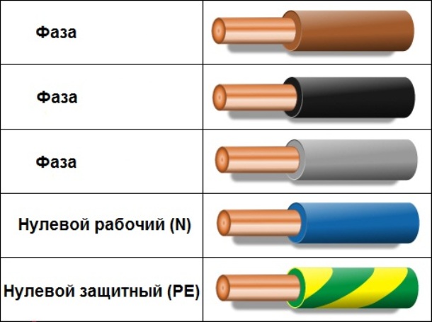
Most often for phase wires, the following color is used:
- Red;
- The black;
- Brown;
- Orange;
- Lilac
- Pink;
- Purple;
- White;
- Gray.

Phase wires can be painted in these colors. You can easier to deal with them if you exclude zero wire and land. For convenience, in the diagram, the image of the phase wire is made to denote the Latin L. L. if there is not a single phase, and several, a numerical designation must be added to the letter, which looks like this: L1, L2 and L3, for three-phase in 380 in networks. In some performances, the first phase (mass) can be indicated by the letter A, the second - b, and the third - C.
What color ground wire
In accordance with modern standards, the ground conductor must have yellow-green. It looks like yellow isolation, on which there are two longitudinal bright green stripes. But sometimes there is a coloring from the transverse green and yellow strips.
Sometimes, only bright green or yellow conductions can be in the cable. In this case, the Earth will be denoted by this color. The corresponding colors it will be displayed in the diagrams. Most often, engineers are drawn from brightly green, but sometimes yellow conductors can be seen. Denote in Latin (in English) letters in Latin (in English) Latin (in English) letters. Accordingly, the contacts are marked, where the "earth" wire must be connected.
Sometimes experts call the grounding wire "zero and protective", but do not confuse. If you see such a designation, then you know that it is the earthen wire, and it is called it because it reduces the risk of shock.
Zero or neutral wire has the following marking color:
- Blue;
- Blue;
- Blue with white stripe.
No colors in the electrician for labeling zero wire are not used. So you will find it in any, whether it is three-core, pentolous, and maybe with even more conductors. Blue and its shades are usually drawn "zero" in various schemes. Professionals call it working zero, because (which cannot be said about grounding), participates in electrical wiring with food. Some, when reading the scheme, call it minus, while the phase everyone considers "plus".
How to check the connection of wires by colors
Wiring colors in electricity are invented in order to speed up the identification of conductors. However, it is only dangerous to rely on the color, because any newcomer, or an irresponsible worker from ZhZK-A, could connect them incorrectly. In this regard, before proceeding with the work, it is necessary to make sure that their marking or connection must be correct.
In order to check the wires on the polarity, we take an indicator screwdriver or multimeter. It is worth noting that the screwdriver is easier to work with a screwdriver: when you touch the phase lights up the LED mounted into the case.
If the cable is two-tissue, then there are practically no problems, you excluded the phase, then the second conductor, which remained, is zero. However, there are often three-core wires. Here, for definition you need a tester, or a multimeter. With their help, it is also not difficult to determine which wires phase (positive), and what is zero.
This is done as follows:
- A switch is displayed on the device in such a way as to select Shakal more than 220 V.
- Then you need to take two probe into your hands, and holding them for plastic handles, very carefully touching the rod of one of the probe to the found wire phase, and the second lean to the alleged zero.
- After that, 220 V will be displayed on the screen, or the voltage that is in fact on the network. Today it may be lower.

If the display appears the value of 220 V or something in this limit, then the other wire is zero, and the remaining - presumably "earth". In case the value that appears on the display is less, it is worth checking. One dipstick again touches the phase, to others to the alleged ground. If the instrument readings are lower than in the case of the first dimension, then you are "earth". According to standards, it should be green or yellow. If suddenly the testimony turned out to be higher, this means somewhere sounded somewhere, and in front of you "zero" wire. The exit from this situation will either search for exactly where the wires connected incorrectly, or leaving everything as it is, remembering that the wires are confused.
Wire designations in electrical circuits: Connection features
Starting any electrical work on the lines where the network has already been laid, you must make sure that the wires are connected correctly. This is done with the help of special test devices.
It is necessary to remember that when checking the Phase-zero connection, the indicator multimeter will always be higher than in the case of the Phase-Earth pair.
Wires in electrical circuits on standards have color marking. This fact allows the electrician in a short period of time to find zero, grounding and phase. In the event that these wires are incorrectly connected, then a short circuit will arise. Sometimes such an oversight leads to the fact that a person gets a blow to an electric shock. Therefore, it is impossible to neglect the rules (PUE) of the connection, and it is necessary to know that the special color marking of the wires is designed to ensure safety when working with electrical wiring. In addition, this systematization significantly reduces the operation time of the electrician, as it has the ability to quickly find the contacts you need.
Features of working with electroplating of different color:
- If you need to install a new one, or replace the old outlet, then it is not necessary to determine the phase at all. Fork, it does not matter at all, from which side you connect it.
- In the case when you connect the switch from the chandelier, you need to know that it must be supplied specifically a phase, and only zero to the light bulbs.
- If the color of the contacts and phase and zero is completely the same, then the value of the conductors is determined using an indicator screwdriver, where the handle is made of transparent plastic with a diode inside.
- Before determining the conductor, the electrical chain in the house or other room should be de-energized, and wiring at the ends and dilute to the sides. If this is not done, they can inadvertently in touch and get a short circuit.
The use of color marking in the electrician much facilitated the life of people. In addition, due to the color notation, safety has risen when working with wires that are under voltage.
Designations and colors of wires in electrics (video)
Rating 4.50 (1 voice)
In electrical installations and household electrical networks, conductors who have different purposes are used. The main of them used to transmit electrical energy are phase voltage conductors, zero working and zero protective.
All of them must be identified. Otherwise, even in the presence of fundamental, installation or single-line schemes, explaining, to which contacts of the electroapplents they are connected, it will be impossible to understand. And the need for this arises constantly.
Another important reason that requires the identification of conductors - electrical safety. Touching any current-handing parts, not even under life-threatening potential, is prohibited without checking the absence of voltages on them. But plots of chains containing both dangerous and safe potentials should be clearly designated. This is one of the numerous components of the organization of safe operation of electrical installations.
Identification of conductors of power electrical circuits is made in two methods:
- conductors are painted in colors corresponding to their appointment;
- at the ends of the conductors or on all of them there are alphabetic notation, unambiguously determining the functional purpose.
The rules for applying color and alphabetic marking on conductors used in power circuits are set out in detail in GOST R 50462-2009. Despite the fact that it has the status of the National Standard of the Russian Federation, it completely repeats the IEC 60446-2007 standard. Thus, the rules for applying labeling of wires in Russia are given to compliance with European standards. The relevance of this is dictated by the fact that Western equipment, manufactured by European standards, is available to Russia, and therefore, for its correct operation, our own rules should be aligned with IEC.
So, we will now understand how the colors of the wire and cable veins are for use in various circuits.
Marking of phase conductors
All electrical networks can be divided into:
- single-phase;
- three-phase;
- dC network.
Each of them provides their rules for marking conductors. Let's start with phase.
In single-phase chains, all phase conductors according to GOST should have brown. However, this does not mean at all that when installing a single-phase distribution panel, it is necessary to apply such wires. Their color does not have to be brown, but any, but not blue or yellow-green. Additionally, on the ends of the conductors, marking with a L1, L2 or L3 letter can be applied, which indicates which phase of the three-phase network is connected to this shield.
However, if this single-phase chain is branched off from three-phase as part of a device or a shield, the color of its conductors must correspond to the color of the wires of the phase to which it connects: brown, black or gray.
In brown, blue and yellow-green colors painted cables for mounting single-phase networks.
Phase wires in three-phase networks used to be labeled as letter notation: A, B and C. In addition, the authentication tires were stained into the corresponding colors:
- phase A - yellow;
- phase B green;
- phase C - red.
Now GOST prohibits the use of green and yellow for labeling, as they can be confused with yellow-green, having a different destination that will be described further.
Wires were not taken to be labeled at all. An example of this example is the drive junction pads. They have all the wires: and phase, and zero - the same. An attempt to determine their purpose is conjugate with some difficulties: it is even possible to conclude that the conductor is connected to the phase of the supply network, it is possible with confidence only when it has a voltage, and in your hands - indicator. Be sure that the conductor is zero, it is impossible never.
Therefore, the GOST for phase conductors is prescribed next labeling.
| Phase wire | Letter | Color |
| Phase A (phase 1) | L1 | brown |
| Phase in (phase 2) | L2. | the black |
| Phase C (phase 2) | L3. | grey |
Wire label is allowed by any of two ways or both at once. In the first case, tags with alphabetic designation are attached at the ends of the wires, in the second - the corresponding coloring of the current-carrying parts is used. Strictly speaking, use in camshafts when installing wires that have brown, black and gray colors are not at all necessary. The binding to the color is more relevant to the cable lines, since their veins are painted in brown, black, gray, blue and yellow-green. When connecting cables to terminals, consumers or to the conclusions of electrical apparatus, it is necessary to comply with the requirements of GOST.
To assemble the panel products, the installation of phase circuits is allowed to perform with one-color wires, while observing the conditions:
- it is impossible to use blue;
- it is impossible to use yellow-green color;
- the labeling of the letter notes caused to the beginning and end of the wire is required.
Western manufacturers do not paint tires in brown, black, gray, as well as blue and yellow-green, denoting them with alphabet marking. At the same time, the cost of assembling the panel products and complete distribution devices is slightly reduced. But in return, there is a disadvantage: in order to find out the destination of the tire, you need to find the nearest marking plate on it or take advantage of the PUE knowledge, where the requirements for the relative position of the tire are indicated. But there are electrical installations in which the phase alternation cannot match PUE. Therefore, when labeling tires, stick plates need as often as possible. GOST is prescribed within the panel or shield to label the minimum twice: at the bus inlet in the panel and at the output, or at its start and end.
Marking guides "Earth" and zero
Here, the requirements for labeling are much tougher, as it is directly connected with electrical safety.
Protective zero (or land), as well as current-carrying parts intended for the potential equalization system, are marked with alternating yellow and green stripes. For tires it is a uniform alternation of the strips of yellow and green colors, the wires and cable veins are painted at the factory accordingly.
Use yellow-green, as well as blue color for labeling other chains, as well as labeled a protective zero with other colors, is prohibited.
For alphabet labeling, the Land Wire provides for the designation of RE, for the conductor of the potential equalization - GNYE.
Working zero labeled using only blue color. Other labeling, as well as the use of blue for other purposes, is prohibited. The working zero is denoted by the letter N.
It is a bit more difficult to label zero combined, which is assigned to the designation PEN. Since it combines the functions of the "Earth" conductor and the working zero, and during the labeling it is taken into account. It is permissible to use two ways similar to each other: either to take a wire having a blue color, and apply yellow-green marking at its ends, or at the ends of the yellow-green wire, it is blue. This can be done either with the help of an insulating tape, or a heat-shrinkable tube.
Tires for identification can be not painted along the entire length, since such a method is difficult for these chains. On tires intended for connecting the "Earth" and zero conductors, a lot of holes are performed for connecting them, which makes solid color difficult, and at times - and impossible. It is allowed to apply color strips with blue or yellow-green colors along the edges of the tire.
In today's time it is impossible to mount wiring without using different wire colors(Color isolation of conductors). The color marking of the wires is not something like marketing strokes for tiping clients or decorating products.
In fact, different colors of wires are an urgent need, since the labeling of the wires helps learn the purpose of each of them in a specific group to facilitate switching. Also, during the isolation, the risk of error in the process of installation of wires, and, accordingly, the occurrence of a short circuit with a trial inclusion or lesion in the process of repair and preventive works of networks during the repair and preventive work of networks is also reduced.
The colors selected for the marking of the conductors are specifically selected and supervised by uniform PUE standards. These standards indicate that conductors' veins should be distinguished by alphanumeric or color notation.
This article will tell us about the value of the color of the wire. It is worth noting that the work on the switching of conductors has simplified after the adoption of uniform color identification standards. Each living, with a specific purpose now is indicated by a unique color, for example: blue, yellow, brown, gray, etc.
Often, the color marking is applied along the entire length of the conductor, but also allowed to identify at the points of the connections or at the ends, it was used for this, it is used to be used (colored heat shrink tubes) or a tape of different colors. In order to avoid unnecessary work type of labels using tubes or tape, it is enough to correctly determine the color marking of isolation. It should also be purchased in the desired quantity to provide the same layout of the wiring throughout the apartment or all over the house.
Below will be considered as changing the color of the wirein a constant, single-phase and three-phase current network.
Tires and wires with variable three-phase current.
In power plants and substations in three-phase networks, high-voltage wires and tires are painted in this way: the phase "A" is yellow; Phase "B" - green, and the Phase "C" is red.
What color of the wires "+" and "-" in the DC network:
In addition to the AC networks, the DC circuits are widely used. DC circuits apply to:
1. In construction, when using loaders, electric shocks and electric cranes, as well as in industry.
2. In the electric transport - trams, trolleybuses, electric locomotives, boats, etc.
3. On electrical substations - for supplying automation energy.
Only 2 wires are used on the DC network, since there are no phase or zero conductor in such networks, and there is only a positive and negative tire (+ and -).
According to regulatory documents, wires and tires that have a positive charge (+), and wires and tires with a negative charge (-) are marked with blue. Blue color indicates the average conductor (M).

The positive conductor of the two-wire network is marked with the same color as the positive conductor of the three-wire network, with which it is connected only if the DC double-wire network is created through a double-wire DC network.
Wire color in electrical wiring: land, phase and zero.
To eliminate confusion and simplify installation work when laying an AC power grid, multicore wires in multi-colored isolation are used.
Color designation wires It is especially important when the wiring makes one person, and the maintenance or repairs is different. Otherwise, he will have to constantly check where the phase, and where zero with the help of a probe. Those who worked with the old wiring know how much it can bother, because previously there was only white or black insulation. Since the USSR, the color designation of the wires constantly changed until a special standard was defined. Now each color of the conductor determines its purpose in the wire.
At the present time, the regulatory document is Pue 7, which regulates the color marking of the isolated or uninsulated conductors, where, according to the Identification of the conductors or digital notation, only certain designations and colors should be used.
The main purpose of making the wiring marking is the ease and speed of determining the purpose of the conductor along the entire length, which actually is one of the dominant requirements of PUE standards.
Below will be discussed which coloring should be conductor of alternating current electrical installations, voltage up to 1000V and with a deployed neutral (for example, the wiring of administrative buildings or residential buildings).
The color of the zero working and zero protective conductor.
Zero working conductors (N) are designated blue. The zero protective conductor (RE) is marked with yellow-green transverse or longitudinal stripes. Such a combination should be used exclusively for marking grounding conductors.
Combined zero working and zero protective conductors (PEN) - blue color over the entire length of the cord with yellow-green stripes in the connecting places or at the ends. It is important to mention that GOST today allows the opposite color option, that is, yellow-green stripes with blue in the connection places.

If we generalize, then color wiremust be distributed like this:
1. Combined (Pen) - yellow-green with blue tags at the ends;
2. Zero worker (N) - blue (blue) color;
3. Zero protective (re) - yellow-green.
Colors of phase wires.
According to PUE, when labeling phase conductors, you need to give preference to such colors: turquoise, black, orange, brown, white, red, pink, gray or purple.

It is known that a single-phase electrical chain can be created by a method of branch from three-phase, in this case the color of the single-phase chain phase wire must coincide with the color of the three-phase chain phase conductor.
Color designation of insulating coating conductors It should be carried out in such a way that the color of the phase conductor was easily distinguished from the color of the N, PE or PEN conductors. In the case of using a non-marked wire, color identifiers are set in places of connection or at the end.
When working with electricity, a large number of cables of different sizes and colors are used. To always pick up the right product, there is marking wires in colors. Thus, individual cables are always designated in the same color for convenient use. For example, the color of the ground wire is always made in green-yellow isolation, and the color of the phase is green. This allows you to determine the purpose of the wire without tests and do if necessary with a different branch.
In the event that there are several phases and zero wires in the network, they are marked with flowers according to the zero of the rules for working with electricity. Usually it is coloring, close to the main color, but depending on the network they may differ.
electrical safety
A variable electric current voltage 220 V or 380 V is dangerous for a person. Careless touch to bare wires or metal parts of electrical equipment that can be under voltage is fraught with heavy burn or mortal injury!
For this, PUE gives an answer not only to questions: what color is the ground wire, or what is ren, but why it is necessary.
- In order to maximize the person from the possible effects of electrical workers, electrical safety systems were adopted, characterized by one or several factors, such as:
- grounding;
- protective reassembly;
- separating networks with a transformer.
To ensure safe operation in the current electrical installations up to 1 kV, five ground systems are used: TN-C, TN-S, TN-C-S, TT, IT with different ways of grounding, reassembling and separating networks.
- PUE determines each of the systems as:
- TN-C, where the working zero n and the grounding re were connected in one wire ren. It is characterized by: using a cable with four cores in a three-phase network and a two-tissue cable in a single-phase. This is the oldest device of the power grid, is still everywhere, for considerations of savings, for example, in street lighting.
- TN-S, where the working n conductor and grounding re are separated from the supply transformer and to the end user. Such networks are made from pental cables for a three-phase network and three-core wires in a single-phase network.
- TN-S-S, where there is one combined rein conductor of four cores, from the supply transformer to a group panel at entering the building, which is then divided into N and re, respectively, on five and three-core wiring. This is the most common system for constructing power supply networks of buildings and structures.
- TT, where there is only one worker N conductor, and only the body of electrical equipment is grounded. In such a system, four and two-housing wiring are used, respectively. So, mainly air lines are arranged.
- IT, where the electrical installation is separated from the power supply of the power supply and is completely isolated from the ground. This is the safest system for a person, applies to consumers only special purpose.
Thus, the color of the wires of the phase and zero, L and N in the electrician will help to clearly define the applicable security system in this electrical network.
Specificity of various types of cable products
Before taking a conversation about the marking, it is worth determining what is the difference between cable, wire and cord. Various types of cables can be used not only on the surface, but also under the ground, and in water. This is possible because one or more isolated veins are protected by a special shell, which can be made of various materials capable of withstanding aggressive conditions of the external environment.
As for electrical wires, they also have twisted or isolated wires or veins. They are covered with a protective non-metallic shell or winding that does not imply their gasket in the ground.
The cord is called the wire in which there are flexible and insulated veins. With this type of cable products, a network is connected to a network of various household devices, devices that are moving or often moved from place to place.
- Classification of cable products depending on the purpose looks like this:
- Power products. These include the wires of SIP and VG. The last species is suitable for mounting wiring and lighting indoors, connecting electrical installations. The self-supporting insulated wire (SIP) is used in the construction of air lines and the creation of branches to residential buildings and buildings. The number of conductive livers in products with labeling VG varies from 1 to 6. For a sip variety, this indicator ranges from 1 to 4.
- The assignment of radio frequency cables is the transmission of the signal from one device to another.
- The control facilities are needed to power devices and are indispensable in remote control systems. GOST allows them the number of conductive lived from 4 to 37 pcs.
- To coordinate the operation of devices and devices at a distance, the control wires are applied along with the control specimen. Current livers in such products can be from 3 to 108 pcs.
- A separate type of communication cable will be required to ensure that the subscribers have the opportunity to exchange information at a distance. Inside this group, there is a separation for high and low-frequency types of products.
What is needed labeling
Specific colors in the electrics are not chosen. Color wiring is necessary for safe conducting electrical work to avoid short circuit and electric shock. Previously, the color of the conductors was black or white, as a result of electricians, it brought great inconvenience.
In compliance, it was necessary to supply power to the conductors, after which the control was determined by zero and phase. The use of colors got rid of all these flour, because everything became very clear.
Color marking is almost always applied along the entire length of the conductor. It helps to set the purpose of each conductor to a specific group to facilitate their switching. There are three types of wires in an electrician: phase, zero and grounding.
To ensure clarity, simplicity and facilitate recognition of individual parts of the electrical network according to claim 1.1.30 Pue, all electrical installations must have alphanumeric and color designation. Moreover, the presence of one of these designations does not remove the need for the other.
Color marking
Marking of collar wires is the most visual and allows you to quickly decide on the assignment of any wire. Such marking can be carried out by selecting wires with the appropriate color of insulation lived, by applying paints to the tires or by staining or applying a special color tape in the connection locations.
Moreover, the paint on the tires can not be applied along the entire length, but only in places of connection or at the ends of the tires.
- So:
- If we talk about the color designation of wires and cables, you should start with phase conductors. According to paragraph 1.1.30 Pue in a three-phase network, phase conductors must have a marking yellow, green and red. So, respectively, phases A, B and C.
- The instruction for a single-phase electrical network involves the designation of the phase wire according to the color, the continuation of which it is. That is, if the phase conductor connects to the "B" phase of the three-phase network, then it must have a green color.
- As for zero conductors, they must have a blue color. Moreover, the color of the zero core does not depend on that three-phase, two-phase and single-phase network in front of you. It is always denoted by blue.
- Marking of wires with a yellow-green strip denotes a protective conductor. It connects to the electrical appliance housing and ensures safety from electric shock when electrical equipment isolating is damaged.
- If the zero and protective conductor are combined, then according to claim 1.1.29 PUE, such a live wire should have a blue color with yellow-green stripes at its ends. In order to perform such labeling with your own hands, it is enough to just take the wire of the blue color and on its end sealing to perform the designation of paint or use the color isolate to be used for this.
- As for DC networks, the positive livelux of wires or tires should be designated in red, and negative blue. In this case, the designation of zero and protective core meets the labeling in the AC networks.
Note! In a single-phase apartment network or at home, you often do not know which phase your phase wire is connected. In order to comply with GOST, you do not need to find out at all. It is enough to designate the phase conductor in any of the proposed colors. After all, for a single-phase lighting network absolutely not fundamentally to which phase is your conductor connected. The exception is only the lighting network, which uses two different phase conductor.
Local marking of wires
But color marking is not always convenient. In the shields, and the schemes are much more convenient. It should be applied in conjunction with color designation.
- So:
- The letter marking of phase wires in the three-phase network corresponds to their conversational notation - the phase "A", "B" and "C". For a single-phase network, it should be the same, but it is not always convenient. Especially since it is not always possible to reliably determine which phase is not always possible. Therefore, the "L" designation often uses.
- If the wire marking in the shield is performed, then under the symbol "n" denote zero wire.
- To designate the protective wire, the letter designation "PE" apply. In addition, a grounding sign is often used, but the fact is that it does not always be accurately indicated on the network scheme.
- The fact is that you can meet the designation "PEN". It denotes the alignment of the zero and protective conductor. This is possible in the TN-C-S systems about which we talked in one of our previous articles.
- But the marking of electrical DC wires is performed by symbolisms "+" and "¬-". What respectively denotes a positive and negative wire. For DC there is another difference. Zero lived is indicated by the symbol of "M", which is sometimes misleading.
Paragraph 1.1.31 PUE normalizes not only the alphanumeric designation of conductors, but also their location. So for the three-phase network, with a vertical location of the tires, the phase "A" should be the top, and the "C" phase "C". And with the horizontal location of the conductors, the closest to you should be the "C" phase, and the most remote phase "A".
What designs the colors of the wires in the electrics
Color isolation of conductors today is an integral attribute for the successful and proper installation of wiring. Such a solution is not a way to make wires beautiful and attractive to the consumer, it is a convenient color marking, standardized and regulated in the entire civilized world, which is without exaggeration, necessity.
Color marking of wires gives accurate designation to each conductor. The color of the insulation of the core determines its purpose in the group of several conductors and facilitates the switching process and installation.
Such a solution eliminates possible errors that can lead to a deadly electric shock or short circuit. The repair and maintenance of the power grid is also becoming more secure if the wires have accurate labeling.
The standard set forth in PUE strictly determines the color of the marking, and thanks to this standard it is possible to easily identify each conductor, each cable vein in the color group or by alphanumeric code.
As a rule, the entire conductor has a certain color, but allowed and marking only the ends of individual lived, at the dials of switching, where the use of colored tape or colored Cambriks is possible. Next, we will consider in more detail how it is that such marking for single-phase, three-phase current and direct current networks.
Standard color marking of tires and wires for three-phase alternating current networks
- In three-phase AC networks, high voltage of transformers both at stations and substations, as well as tires, painted in the following colors, respectively phases:
- Phase "A" - painted in yellow color;
- Phase "B" - painted in green;
- Phase "C" - painted in red.
Standard color marking for wires and bus networks of DC
For DC chains, only two tires are characterized: positive and negative. Here, the positive wire (positive charge bus) is marked with red, and the negative wire (negative charge tire) is marked with blue, because the zero and phase wire here are fundamentally missing. The average wire (m) is marked with blue.
In the case when the DC network containing two conductors is created by branches from the three-wire DC circuit, the conductors are marked as well as the corresponding conductors of the original three-wire chain.

Electric AC networks are now paving now the stranded wire in isolation lived in different colors, it greatly facilitates the installation process. If one installer performs one installer, and in the future, the maintenance and repair of the network will carry out other people, they will not be forced to constantly identify the "phase" and "zero", they simply are ignited by color.
But in the old days it was a real problem, for isolation was used single-color - or white, or black. Now the standard has been developed, and in accordance with GOST R 50462 "Identification of conductors on flowers or digital notation", residential veins and cables have strictly regulated designations.The label function is to create the possibility of a quick and easy visual definition of the purpose of each specific conductor on any of its plot, this is one of the main requirements of the PUE. What color, according to GOST, should conduct conductors in the electrical installations of AC voltage to 1000 volts and with a deaf-earth neutral, which include almost all residential buildings and administrative buildings?
Zero working conductor (N) has a blue label. For zero protective conductor (PE) - yellow-green labeling in the form of strips along or across the veins. This marking in the named combination of colors is relevant only for grounding conductors (for zero protective).
When a zero working conductor is made combined with zero protective (PEN), then along the entire length of the wire marking is made in blue, and in the places of attachments (at the ends of the conductor) - yellow-green stripes, or vice versa: yellow-green conductor with blue ends.
- So, zero wires are marked with the following colors:
- Zero working wire (N) - marking in blue;
- Zero protective wire (PE) - labeling yellow-green color;
- Zero combined wire (PEN) - marked with yellow-green color with blue tags at the ends or vice versa.
Phase wires, in accordance with the PUE standard, can be marked with one of these colors: red, black, purple, brown, gray, pink, orange, turquoise, or white. If a single-phase electrical circuit is obtained by branching from a three-phase network, the phase wire of the obtained single-phase chain must necessarily coincide with the color with the source wire of the three-phase network, which produced a branch.
The wires are marked so that the colors of phase wires in no way coincide with the color with a zero conductor. And if a non-marked cable is applied, then the color marks are made at the ends of the veins, in places of compounds, with the help of cembos of heat shrink or color tape. But to prevent unnecessary work on the manufacture of labels, it is quite initially to choose the color of the insulation, selecting the cable of sufficient length for its needs.
Sometimes the electrician in the work has to face with not very pleasant situations when the wiring has already been performed, and no connection in the shield, nor wires are marked, in this case a person has to spend time and, using a probe, identify the "phase", "zero", and "Grounding".
However, it should always be remembered that even if it is not possible to purchase the wire of the desired color, you can certainly use the wire of any color, but then it is necessary to mark the ends core at least a color heat shrinking or color tape. And always remember that when laying wiring it is necessary to be careful and always follow safety.
Marking of aluminum cables
ADPV 2x6-380 is a wire aluminum coated from PVC, flat, has a separator (about determination slightly lower), 2 veins with a cross section of 6 mm. It should be noted that the letter notation is used mainly for high-voltage options.
Color marking helps to determine the destination of the cable. It is used for telephone cords, household appliances (fan, video cameras), vehicles (VAZ and other), etc. It is these data that is most important when installing cables or.
- How to determine the purpose and types of wires on color marking, according to Pue 7:
- Blue - working zero;
- Green is zero protective;
- Black - grounding or "earth";
- White is the color marking of the wires of the zero phase.
By the way, different manufacturers may have different types of designations. For example, a phase cable can be white, pink, yellow, orange, gray, red, so be careful when installing or removing cords. When the phase or outlet is connected, make sure that the colors of the cables are coincided.
Marking of individual electrical cables
Each household device uses a kind of designation system.
- Keyboard for a laptop or computer power supply:
- Red - standard USB VDC, Defender Accord KM-4810L keyboard connection wire and other.
- White - for USB D connector, while green is defined by D +.
- Black - designed to enter GND (in headphones).
Be careful, black and red wires are also used to connect the cooling cooler for electrical equipment.
- For which the wires of tape recorders are answered:
- Black - Earth or Connection to Masse Engine.
- Red - power cord.
- Yellow - meal, connects with red.
- Blue (if any) - control of the antenna and other functions of magnetic pipelines.
Buy Wires of the desired type (SIP, mounting, flexible and other) in specialized stores, where marking is also indicated in the certificate and passport of the product. The price depends on the type of cord.
Wiring inside the house
Wiring inside the house is performed only by single-phase lines and copper wires. In electrical circuits used for household purposes, the working zero should always be blue! According to PUE, garbage lines must be laid with a grounding conductor. In all three-core conductors, made according to GOST, suitable for internal works, ground wire - yellow-green.
If the three-core conductor is a flexible PVS type, then the phase conductor is usually brown. For domestic wiring it is better to use wires made of cast copper. If the veins are tagged with stripes, she lived with a strip of any color excluding blue and yellow green - phase.
If there is no yellow-green conductor in the cable, the conductor with a green strip is used as a grounding wire. Ground wire can be marked purely yellow. In cables whose veins are painted entirely, the white wire is phase.
Powerboard to electric stove
Household electric stoves by 220 V connected to a special outlet, withstanding high power. Color there is a red, green, blue, where red - phase, green - ground, blue - zero conductor.
- There is a nuance, in electric stoves and cooking surfaces of foreign production, designed for 220/380 V, the connection is performed by a four-core cable:
- blue - zero;
- yellow-green conductor - grounding;
- black conductor - phase A;
- brown conductor - Phase V.
It is allowed when connecting to one phase network to combine the phase conductors on the electric stove under one pin clamp.
Neutral wire
The neutral conductor is a wire attached to the middle (zero) point of the electrical system. In the standard connection scheme, this is a combined zero working and zero protective conductor in three phase chains. The color of the neutral wire is the whole blue with yellow-green at the ends or all yellow-green with blue at the ends.
Wiring marked color, letters and numbers is carried out. GOST until 2009, more widely interpreted the possibilities of marking wires. Starting in 2009, standards are reviewed towards a clearer classification of colors and exclude notes that allow you not to label conductions.
The National Standard 2009 refined terminology and supplemented with an alphanumeric classification. For electrical chains until 2009, a classic hand painting was used: yellow, green, red.
- In the classic version of three-phase circuits up to 1000 volts, conductors are tagged in the following combinations:
- Phase A - L1, Yellow - recommended brown.
- Black is recommended in phase in - L2, green.
- Phase C - L3, red - recommended gray.
- Zero conductor - N blue.
- Combined working zero with ground conductor - Pen, blue with yellow-green tips - yellow-green with blue tips.
- Ground conductor - PE, yellow-green.
This combination does not imply a direction of rotation or a phasing.

From the junction box to the switch, a three-core or two vehicle wire is paved depending on which type of switch is set: a classic or. Phase is breaking, not a zero conductor. If there is a white conductor in stock, it will be powered. The main thing is to comply with the sequence and consistency in coloring with other electrical installations so that it does not work as in the Krylov Basna: "Swan, Cancer and Pike".
On the sockets, the protective conductor (yellow-green) is most often clamped in the middle part of the device. Observe the polarity, zero working - left, the phase is right.
But there are surprises from manufacturers, for example, one conductor is yellow-green, and two others may turn out to be black.
Perhaps the manufacturer decided with a shortage of one coloring, to put into the course of what is. Do not stop the production! Failures and mistakes are everywhere. If it was exactly the one where the phase, and where zero to solve you, just need to run with the control.
If the cable is already laid, how to label
Very often, it is necessary to deal with such situations when you come to the object, open the shield, and there the connection is made incomprehensible as. There is no talk about matching the marking of wires with the rules in general. It is not clear how the phase is laid, and where zero and grounding.
You have to be familiar with the wiring of the wires in the shield, junction boxes, etc. It all comes down to one lack of time, you have to spend time. How to be in this case? Do not make the connection in a new way.
Unfortunately, even today, some electricians during installation work enjoy outdated standards. Because of this, other specialists during the work related to the repair and maintenance of electrical networks have to look for the "phase" and "zero" with the help of a probe.
If there is no possibility to buy the guides of the desired color, cables are suitable for any color. The main thing is that the ends of the veins are correctly marked with heat shrink tubes or color tape.
In accordance with the rules, it is allowed to perform the color marking not along the entire length, but only in the connecting places to the tires, that is, at the ends of the cable. To do this, you can perform the designation of wires in color using the color tape or put on the ends of the cable with a heat shrink tube.
Of course, there is no need to change the existing marking of the conductors, the installation of which was carried out according to the old GOST. But today, when putting the electrical installations, only new rules should be used.
We remind you: work on the laying of an electrical cable requires foregraded and attentiveness. Be careful!
Wires in electrical wiring have color marking, which allows the electrician to quickly find zero, phase and grounding. If these contacts are incorrect to be connected to each other, then a short circuit may occur, and in some cases the person affects the electrical current. Therefore, color marking of wires creates safe conditions for electrical work, and besides this, significantly reduces the search and contact connection time. Currently, according to the rules of the electrical installation device (PUE) and the necessary European standards, each wire is required to have its own definite color.
What is needed colored wires
Specific colors in the electrics are not chosen. Color wiring is necessary for safe conducting electrical work to avoid short circuit and electric shock. Previously, the color of the conductors was black or whiteAs a result, electricians brought great inconveniences. In compliance, it was necessary to supply power to the conductors, after which the control was determined by zero and phase. The use of colors got rid of all these flour, because everything became very clear.
Color marking is almost always applied along the entire length of the conductor. It helps to set the purpose of each conductor to a specific group to facilitate their switching. There are three types of wires in an electrician: phase, zero and grounding.
What does ground wire and zero look like
According to PUE, ground wire It has the following colors:
- yellow-green;
- yellow;
- green.
It should be known that the manufacturers also apply a yellow-green strip in the longitudinal and transverse direction. On the electrical circuit, the grounding is denoted by Latin lists "PE". Quite often, the ground is called zero protection, and it is impossible to be confused with zero workers.
In single-phase and three-phase power grid wire zero is usually denoted by blue or blue-white Color. On the electrical circuit, Zero is indicated by the Latin Literary "N". Zero is also called neutral or zero working contact.
The marking of the phase wire (L) is presented in the following color solutions:

But most often the phase conductor has brown, White and Black Color.
How to distinguish zero and "land"
The zero from grounding is characterized by the fact that it takes an electric current during it during the connection of the load, and the "land" is used to protect against damage to the current, which does not flow through this conductor, and connect to the instrument enclosures.
Wires "Earth" and zero you can be distinguished by the following ways:
- With the help of an ohmmeter, resistance is measured on the "Earth" conductor (which usually does not exceed 4 ohms). Before it should be ensured that there is no voltage between measurement points.
- Using a voltmeter, in turns measure the voltage between the phase conductor and the two remaining wires. At the same time, "Earth" always has a great value.
- If it is necessary to measure the voltage between the "earth" and any grounded device (for example, the central heating battery or the electrical panel body), then the voltmeter will not show anything at all. And if the same way to apply to zero - there will be a small tension.
If the wiring has only 2 wires, it will always be a phase and zero.
 If you need to install or replace the outlet, definition phase is completely optionalbecause it does not matter, from which side it is connected. It is completely different with the switch from the chandelier, because it must be supplied to it by the phase, and only zero to the lamps.
If the color of the wires of the valve phase is completely the same, then the conductors are determined using an indicator screwdriver, which has a handle made of transparent plastic, and the diode is installed inside. Before determining the conductors, the room or the house is de-energized, wiring at the ends are cleaned and bred to the sides, otherwise they may accidentally come into contact and a short circuit will occur.
Thereafter connect electricity, take a screwdriver for handle, and index and thumb are put on contact with the back side of the socket. Then it is necessary to touch the metal end of the screwdriver to the cereal wire and trace it for its reaction. If the bulb caught fire, it means that it is a phase, if not - zero. However, this screwdriver will not be able to determine the conductors if the third wire is present - grounding.
Conclusion
The use of color marking in the electrician very facilitated the life of people who, for various reasons, need to know which wires are under voltage. However, it is still worth being attentive when working with electricity, so that there are no sad consequences.