How to make joints on wood surfaces. Ways of joining wooden parts. Elongation with compound rafters
In addition to processing solid pieces of wood, it is often necessary to combine wooden parts into knots and structures. Connections of elements of wooden structures are called landings. Joints in timber structures are defined by five types of fits: tight, tight, sliding, loose, and very loose.
Nodes - these are parts of structures at the joints of parts. Connections of wooden structures are divided into types: end, side, corner T-shaped, cruciform, corner L-shaped and box corner joints.
Joinery connections have over 200 options. Only the connections that joiners and carpenters use in practice are considered here.
End connection (extension) - connection of parts along the length, when one element is a continuation of the other. Such connections are smooth, serrated with spikes. Additionally, they are fixed with glue, screws, overlays. Horizontal end connections withstand compressive, tensile, and bending loads (Figure 1-5). Lumber is built up in length, forming at the ends vertical and horizontal toothed joints (wedge lock) (Fig. 6). Such joints do not need to be under pressure during the entire bonding process, as significant frictional forces act here. Milled sawn timber toothed joints meet the first class of accuracy.
The joints of wooden structures must be made carefully, in accordance with three classes of accuracy. The first class is designed for high quality measuring tools, the second class is for furniture products, and the third is for building parts, agricultural implements and packaging. Lateral connection by the edge of several boards or laths is called rallying (Fig. 7). Such connections are used in the construction of floors, gates, carpentry doors, etc. Plank and rack panels are additionally reinforced with crossbars and tips. When covering ceilings and walls, the upper boards overlap the lower ones by 1/5 - 1/4 of the width. The outer walls are sheathed with horizontally laid overlapping boards (Fig. 7, g). The upper board overlaps the lower one by 1/5 - 1/4 of the width, which ensures the drainage of atmospheric precipitation. The connection of the end of the part with the middle part of the other forms a T-shaped connection of the parts. Such connections have a large number of variants, two of which are shown in Fig. 8. These connections (knitting) are used when joining the lag of floors and partitions with the harness of the house. The connection of parts at a right or oblique angle is called a cruciform connection. This connection has one or two grooves (Fig. 3.9). Cruciform connections are used in roof and truss structures.
 |
| Rice. 1. End connections of beams that resist compression: a - with a straight overlay in a half-tree; b - with an oblique overlay (on the "mustache"); c - with a straight overlay in a half-tree with a joint at an obtuse angle; d - with an oblique lining with a spike joint. |
 |
| Rice. 2. End connections of beams (build-up) that resist stretching: a - in a straight laid on lock; b - in an oblique patch lock; c - with a straight overlay in a half-tree with a joint in an oblique thorn (in a dovetail). |
 |
| Rice. 3. The end connections of the bending resisting beams: a - with a straight overlay in a half-wood with an oblique joint; b - with a straight overlay in a half-tree with a stepped joint; c - in an oblique patch lock with wedges and a thorn joint. |
 |
| Rice. 4. Splice joint with reinforcement wedges and bolts. |
 |
| Rice. 5. End joints of the bars working in compression: a - butt-end with a secret hollowed-out spike; b - end-to-end with a hidden plug-in thorn; c - with a straight overlay in half a tree (the connection can be bolted); g-with a straight overlay in a half-tree with wire fixing; d - with a straight overlay in a half-tree with fastening with metal clips (clamps); e - with an oblique pad (on the "mustache") with fastening with metal clips; g - with an oblique pad and bolting; h - marking of the slanting lining; and - end-to-end with a hidden tetrahedral spike. |
 |
| Rice. 6. End augmentation of the milling scheme for end gluing of workpieces: a - vertical (along the width of the part), toothed (wedge-shaped) connection; b - horizontal (along the thickness of the part), toothed (wedge-shaped) connection; c - milling a gear connection; d - sawing out the toothed joint; d - milling the gear joint; e - connection to the end and gluing. |
 |
| Rice. 7. Planks rallying: a - on a smooth joint; b - on a plug-in rail; c - in a quarter; d, e, f - in the groove and ridge (with various shapes of the groove and ridge); w - overlap; h - with a tip in the groove; and - with a quarter tip; k - with overlap. |
 |
| Rice. 8. T-shaped joints of the bars: a - with a secret oblique thorn (in a paw or in a dovetail); b - with a straight stepped pad. |
 |
| Rice. 9. Cross connections of bars: a - with a straight overlay in half a tree; b - with a direct overlap of incomplete overlap; c - with landing in one socket |
Connections of two parts with ends at right angles are called angular. They have through and non-through thorns, open and laterally, half-way overlapping, half-tree, etc. (Fig. 10). Corner joints (knitting) are used in incorrect window blocks, in the joints of greenhouse frames, etc. A spike connection in the dark has a spike length of at least half the width of the part to be joined, and the groove depth is 2 - 3 mm longer than the spike length. This is necessary so that the parts to be joined easily mate with each other, and after gluing there is room for excess glue in the spike socket. For door frames, an angular spike joint is used in the dark, and to increase the size of the connected surface, it is semi-dark. Double or triple stud increases the strength of the corner joint. However, the strength of the connection is determined by the quality of its implementation. In the furniture industry, a variety of corner box joints are widely used (Fig. 11). Of these, the simplest is an open end-to-end tenon connection. Before making such a connection, spikes are marked on one end of the board with an awl according to the drawing. By marking the lateral parts of the thorn with a file with fine teeth, they make a cut. Every second cut of the thorn is hollowed out with a chisel. For the accuracy of the connection, first sawed and hollowed out the nests for the studs in one piece. It is placed on the end of another part and crushed. Then they saw through, hollow out and connect the parts, cleaning the connection with a plane, as shown in Fig. eleven.
When connecting parts on a "mustache" (at an angle of 45 °), the angular knitting is fixed with steel inserts, as shown in fig. 12. At the same time, make sure that one half of the insert or fastener goes into one part, and the other half into the other. A wedge-shaped steel plate or ring is placed in the milled grooves of the parts to be joined.
The corners of the frames and boxes are connected with a straight open end-to-end spike connection (Figure 3.13, a, b, c). With increased quality requirements (from the outside, the spikes are not visible), angular knitting is performed by an oblique connection in the direction, a groove and a ridge or an oblique connection on a rail, as shown in Fig. 13, d, e, f, g and in Fig. fourteen.
A box-shaped structure with horizontal or vertical transverse elements (shelves, partitions) is connected using corner T-shaped joints shown in Fig. 15.
In the connection of the elements of the upper belt of wooden trusses with the lower one, corner cuts are used. When the truss elements are mated at an angle of 45 ° or less, one cut is made in the lower element (tightening) (Fig. 16, a), at an angle of more than 45 ° - two cuttings (Fig. 16.6). In both cases, the end cut (cut) is perpendicular to the direction of the acting forces.
Additionally, the nodes are secured with a bolt, washer and nut, less often with brackets. Log walls of a house (log house) made of horizontally laid logs in the corners are connected with a cut "in the paw". It can be simple or with an additional spike (paw with a pit). The marking of the cut is performed as follows: the end of the log is cut into a square, to the length of the side of the square (along the log), so that after processing a cube is obtained. The sides of the cube are divided into 8 equal parts. Then, 4/8 part is removed from one side from below and from above, and the remaining sides are performed, as shown in Fig. 17. Templates are used to speed up the marking and the accuracy of making the cuts.
 |
| Rice. 10. Corner end joints of blanks at right angles: a - with a single opening through a thorn; b - with a single through secret thorn (in the dark); c-with a single deaf (blind) thorn in the dark; d - with a single through semi-secret thorn (semi-dark); d - with a single deaf thorn half-dark; e - with a triple open through thorn; g - in a straight overlay in a half-tree; h - through the dovetail; and - in the eyelets with undercut. |
 |
| Rice. 11. Box corner joints with straight through thorns: a - cutting out the thorn grooves; b - marking the thorns with an awl; в - connection of a spike with a groove; d - processing with a plane corner joint. |
 |
| Rice. 12. Corner end connections at right angles, reinforced with metal inserts - buttons: a - 8-shaped insert; b - wedge-shaped plate; in-rings. |
 |
| Rice. 13. Box corner joints at right angles: a - straight open through thorns; b - oblique open through thorns; c - open through thorns in the dovetail; d - groove on the end-to-end plug-in rail; d - in the groove and comb; e - on plug-in thorns; g - on thorns in a dovetail half-dark. |
 |
| Rice. 14. Oblique (on "mustache") box connections at right angles: a - oblique thorns in the dark; b - oblique connection on a plug-in rail; in - oblique connection on thorns in the dark; d - oblique connection, reinforced with a triangular strip with glue. |
 |
| Rice. 15. Straight and oblique connections of workpieces: a - for double connection in oblique groove and ridge; b - on a straight groove and ridge; в - on a triangular groove and a ridge; d - on a straight groove and ridge in the dark; d - on straight through thorns; e - on round plug-in spikes in the dark; g - on a thorn in a dovetail; h - on the groove and ridge, reinforced with nails. |
 |
| Rice. 16. Nodes in truss elements. |
 |
| Rice. 17. Conjugation of logs from the walls of the log house: a - simple paw; b - a paw with a wind spike; c - paw markings; 1 - wind spike (pit) |
All photos from the article
Sometimes, when carrying out construction and other work using wood, it is required to make the elements longer or wider, and very few know how to do this correctly. That is why we will consider how to splicate the board yourself and what methods and techniques exist. It is important to choose the option that best suits a given situation and requires a minimum investment of time and money.

Basic workflow requirements
Before we begin to consider specific options for carrying out work, it is necessary to understand what factors are observed to ensure that the result is expected to be obtained:
| Material quality | Everything is simple here: it is impossible to make durable structures from low-quality wood, especially when it comes to joints, if they have knots, damage by woodworms, mold and other problems, then there can be no question of any reliability and durability. Choose the best items so as not to waste your energy and money in vain |
| Humidity | Another overriding parameter that should always be considered. Only dry elements are suitable for work, since high humidity, firstly, reduces the strength, secondly, reduces the adhesion of the adhesive composition when using it, and thirdly, after the end of the work, no one will give a guarantee that in a week or a month the structure will not lead or it will not crack |
| Connection loads | It is on this indicator that the choice of one or another connection option largely depends, the greater the load, the higher the requirements for the quality of the pairing and the more complicated the process. Therefore, decide in advance which option will be used in order to guarantee a high result. |
| Using a quality tool | A lot also depends on this, especially when it comes to complex options, when the connection is cut with special devices. They must provide maximum cut quality and maximum joining accuracy, since reliability largely depends on this. |
Important!
Remember one simple rule that experts always use: to obtain the best result, it is necessary that the parameters of the elements to be connected be the same, in other words, one type of wood should be used.
![]()
Work options
All events of this kind can be divided into two large groups - joining boards in width and length, we will consider them separately and tell you which techniques are the most popular and how to implement them correctly.
Width splice
Of course, the simplest solution would be the shield splice option, so we will start with it, first present a diagram of the main options, and below we will describe them in detail:

- The first method involves cutting a cavity with a milling machine, which has a trapezoidal shape and allows you to use the key as a retainer... The plus of this solution can be called reliability, and the minus is the need for a milling machine or the presence of a hand milling cutter for work, you cannot do with a hand tool;
- Joining using an end bar, which is connected to the ends of the board using the groove-comb method, is used for elements of short length, since this option provides high reliability of small structures. Again, you will need it for work. With his help, it will be carried out quickly and efficiently;
- You can make a cutout along the end, fit a rail under it and put it on carpentry glue., it is also quite an interesting option, which is suitable for small structures;
- The last two options involve gluing a triangular strip, only one of them cuts into the end, and the second option involves cutting the end at an angle, you need to choose what is best suited in a given situation.
But if you want to connect the board more securely, then one of the following methods will do:
- The second solution is a connection into a so-called mini-thorn, this is a very durable and reliable option, but for work you will need a special cutter, the price of which is high, so this method is chosen by those who have to splicate elements frequently;

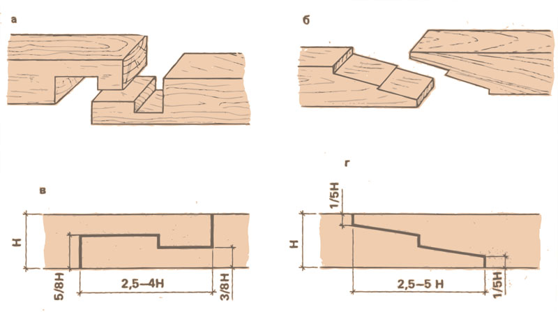
- If the elements are connected in length not in one, but in two or more layers, then you can use the end-to-end option, such a connection of boards along the length is well suited for multilayer systems, in the figure it is under the letter A;
- The traditional version of the groove-comb is often used, here it is important to ensure the optimal configuration of the connection, so the width of the groove and, accordingly, the tongue should not be more than a third of the total thickness of the board, it is important to cut very accurately so that the elements match perfectly, this will significantly increase the strength of the connection;
Important!
When working, a milling cutter is most often used, but cutters can have a different configuration, you should monitor the condition of their cutting edges and sharpen them or replace them in a timely manner, since the quality of the connection largely depends on the cleanliness of the processing.
- You can use the option of cutting at an angle, it is well suited where special strength is not required, but you need to well connect elements that can be used for decoration, etc.;
- The triangular spike-groove is in many ways similar to the usual one, only the configuration of the ends differs. It is also important here that the elements are ideally combined with each other, as this will ensure both the accuracy of the pairing and its maximum reliability;
- The quarter connection is simple - cutouts are made half the thickness, the length of the protrusions should not greatly exceed the thickness, the elements are lubricated with glue and compressed until the composition dries, this is a standard procedure for almost all options;
- The last type is keyed rallying, it does not differ from the above-described option when carrying out work in width, the requirements are the same.
Output
Connecting the board correctly and reliably means ensuring its maximum strength, it is important to follow all recommendations and use only high-quality materials. The video in this article will show some of the options for carrying out the work visually, and if you have questions or additions - unsubscribe in the comments.
Since ancient times, after mastering the tools of labor, man began to build a dwelling made of wood. Having gone through evolution, man for millennia continues to improve the construction of his home. Of course, modern technologies have simplified construction, provided ample opportunity for imagination, but basic knowledge about the properties of wooden structures is passed from generation to generation. Consider ways to connect wooden parts.
Consider the methods of joining wooden parts that novice craftsmen encounter. Basically, these are carpentry connections, passed down from generation to generation, these skills have been used for more than one century. Before we start joining wood, we assume that the wood is already processed and ready for use.
The first basic rule that should be followed when joining wooden parts is that a thin part is attached to a thicker one.
The most common ways of joining wood, which will be needed in the construction of homestead buildings, are of several types.
End connection
This is one of the easiest ways to connect (pull together). With this method, it is necessary to fit the surfaces of the two elements to be connected as closely as possible. The parts are pressed tightly against each other and fastened with nails or screws.

The method is simple, but to obtain the quality of the product, several conditions must be met:
The length of the nails should be such that, having passed through the entire thickness of the first workpiece, they enter the base of another part with their sharp end to a depth equal to at least ⅓ of the length of the nail;
Nails should not be located in one line, and their number should be at least two. That is, one of the nails is shifted upward from the centerline, and the other, on the contrary, downward;
The thickness of the nails must be such that no crack appears in the wood when they are hammered. Pre-drilling the holes will help to avoid the appearance of a crack in the wood, and the drill diameter should be equal to 0.7 of the diameter of the nails;
To obtain a better quality of the connection, the surfaces to be connected should be pre-lubricated with glue, and it is better to use a moisture-resistant glue, for example, epoxy.
Consignment in invoice
In this method, two pieces are stacked on top of each other and held together with nails, screws or bolts. Wooden blanks, with this method of joining, can be placed in one line or displaced at a certain angle relative to each other. In order for the angle of joining the blanks to be rigid, it is necessary to fasten the parts with at least four nails or screws in two rows of two in a row.
If you are fastening with only two nails, screws or bolts, then position them diagonally. If the nails will have a through exit through both parts, with the subsequent bending of the protruding ends, this method of connection will significantly increase the strength. The connection in the invoice does not require high qualifications of the master.
Half-tree connection

This method is more complicated, it requires certain skills and a more scrupulous approach to work. For such a connection, in both wooden blanks, a sample of wood is made at a depth equal to half of their thickness, and a width equal to the width of the parts to be joined.
You can connect parts in half a tree at different angles.
It is important to observe the following rule:
So that the angle of the sample on both parts is equal, and the width of both samples strictly corresponds to the width of the part. If these conditions are met, the parts fit tightly to each other, and their edges will be located in the same plane. The connection is fastened with nails, screws or bolts, and glue is still used to increase strength. If necessary, such a connection can be partial. That is, the end of one of the blanks is cut at a certain angle, and the corresponding selection is made in the other part. This connection is used for corner joining. In this case, both thorns (samples) are cut at an angle of 45 degrees, and the joint between them is located diagonally.
Splice lengthwise
Such splicing of bars and beams along the length has its own characteristics.
For vertical supports, splicing is simple.
But it is a completely different matter when a beam or a beam at the splice is subject to bending or torsion loads, in which case a simple fastening with nails or screws cannot be dispensed with.

The parts to be spliced are cut at an angle (into an oblique pad) and compressed with bolts. The number of bolts depends on the applied loads, but there should be at least two of them.
Sometimes additional overlays are installed, for example, metal plates, preferably on both sides, top and bottom, for strength, you can additionally fasten with wire.
Cleat
Such a connection is used for flooring or for cladding boards. To do this, a spike is made in the face of one board, and a groove in the other.
With such a splicing, gaps between the boards are eliminated, and the sheathing itself takes on a beautiful appearance. Properly processed sawn timber goes to the trade network, where they can be purchased ready-made.

An example of such materials is a floorboard or wall paneling.
Socket-tenon connection
This is one of the most common joining of wooden parts.
Such a connection will provide a strong, rigid and neat cohesion.
It goes without saying that it requires certain skills and accuracy in work from the performer.

When performing this connection, you need to remember that a poor-quality spike connection will not add reliability and will not have a beautiful appearance.
A spike connection consists of a groove, hollowed out or drilled in one of the wooden parts, as well as a spike made at the end of another attached element.
The parts should have the same thickness, but if the thickness is different, then the socket is made in the part that is thicker, and the spike is made in the second, thinner part. The connection is carried out on glue with additional fastening with nails, screws. When screwing in the screw, remember that pre-drilling will make this process easier. It is better to conceal the head of the screw, and the pilot hole should be ⅔ of the screw diameter and be 6 mm less than its length.
One of the very important conditions is the same moisture content of the parts to be joined. If the elements to be joined have different humidity, then when dry, the spike will decrease in size, which will lead to the destruction of the entire connection. That is why the parts to be joined must have the same humidity, close to the operating conditions. For outdoor structures, humidity should be in the range of 30-25%.
Using wood to decorate buildings.
Choice of wood.
In carving, for making large crafts with large elements, they often use softwood as the main one. They are available, and the striped texture can be played up in ornaments.
As a background for the applied and cut threads, it is used fir.

A valuable material is cedar, its soft, with a beautiful texture and pleasant yellow-pink or light-pink color of the core of the wood. The wood is easy to cut, cracks a little during shrinkage and is resistant to decay.

Wood pears It is used for highly artistic thread details, as it is durable and has little warping from weathering.

Poplar, the wood is very soft and light - it is used to make carved decorative columns or backboards for attaching an overhead thread.

It is good to use wood for making chains from round rings. apple trees... This wood is used in small crafts, in applied carving. In this case, the springy properties of the apple tree are used.
Wood is also used linden trees... Very lightweight, planes well, drills and grinds well.

Thread from oak laborious to manufacture due to its hardness.

But the oak is not afraid of moisture, does not warp. Products made from natural wood are very beautiful, but affordable. To reduce the cost of the product, veneering is used. For example, veneered doors are made, according to the customer's order, "oak". We get beautiful doors that are similar in appearance to natural ones, but at a much lower price.
Making furniture with your own hands is gaining more and more popularity due to the high cost of finished products, and due to the large number of raw materials that have appeared in the public domain. At home, with a minimum set of appropriate tools, it is possible to assemble viable furniture that will function properly and delight you with its appearance. One of the most popular connection methods is gluing, which allows you to get strong, monolithic parts. Gluing can be used as an independent fastener or as a duplicate, when using external elements such as pins, dowels or self-tapping screws.
DIY glued wood
Before gluing, the parts are processed, this is done not only to clean the surface, but also allows you to open wood pores. When applied, the adhesive composition penetrates through the pores into the structure of the wood, into the intercellular space, and when solidified, forms a multitude of the finest threads (cobwebs) that reliably "stitch" the workpiece together. The strength of a properly made seam exceeds the strength of the wood itself; when testing for fracture, the part breaks not at the gluing point, but along the solid wood.
Gluing wood allows you to get products with better parameters than massive ones. In the process of gluing, elements that are suitable in texture and shades are selected, damaged, cracked and knotty areas are rejected. As a result, the glued parts have greater strength than ordinary ones, and by gluing the thinnest veneer to the front surfaces, the products are given the appearance of the most valuable species. The wood glued according to all the rules warps, cracks and crumbles much less than the solid wood.
How to glue wood. Technology
There are several ways to join parts when gluing.
- Gluing wood onto a smooth joint - joining smooth parts without increasing the penetration area.
- Gluing on a microthorn - increasing the penetration area by 2.5 - 5 mm due to the creation of a toothed relief on the part (using a router).

- Gluing on a toothed spike - Increases the penetration area by 10 mm by creating a toothed spike.

- Gluing on tongue-and-groove (tongue and groove, dovetail, oblique tenon) - additional grip due to the groove connection.

Although in certain situations, when special conditions of use are assumed, groove and finger joints are relevant, in most cases the parts are glued together on a smooth joint. Modern adhesives penetrate deep into the structure and create a strong joint without additional sampling of wood.
How to glue boards together. Options
The wood to be glued must have a moisture content in the range of 8 - 12%, maximum - 18%. If there is a need to glue wet parts, a special compound is used; during the hardening process, it draws moisture from the tree. When gluing blanks with different moisture content, a drop of more than 2% is not allowed in order to avoid internal stress in the glue seam due to deformation of a wetter part. The temperature of the glued workpieces fluctuates within 15 - 20⁰С, therefore the work is carried out in warm rooms (18 - 22⁰С). In the cold, most compounds crystallize, which leads to a deterioration in the quality of the gluing and complicates the process.
The final preparation of the wood (planing, jointing, sanding) is carried out immediately before gluing in order to increase the permeability of the glue and avoid warping. It is important not only to select parts in terms of size, structure and external data, but also to arrange them correctly.
- When gluing along the length, strips of only one type of sawing are used - tangential or radial;
- When gluing, both in length and in width, alternation of different parts of the wood is not allowed - the kernel is laid with the kernel, sapwood (young, extreme part) with sapwood;
- Annual rings of adjacent blanks from boards or bars should be directed in different directions or at an angle to each other from 15⁰.

The standard thickness of furniture boards is 2 cm, but in order to glue wooden boards at home, when choosing boards for a board, the presumptive processing deviation is taken into account, therefore the workpiece is selected up to 2.5 cm thick. and after gluing, when sanding the board. If you dissolve a board 5 cm thick for a furniture board, you get two blanks with the same texture and shade, which increases the decorativeness of the product. For the boards, boards of wood of the same species are selected, up to 120 mm wide, so that it is possible to process the edges of the board with high quality, the length of the blanks must have a margin (2 - 5 cm).

Adhesives
The adhesives used for the manufacture of laminated timber are divided into two main groups.
Synthetic - obtained on the basis of resins or polyvinyl acetate dispersions (PVA). They are characterized by increased strength of the resulting compound, moisture resistance, and biostability. The disadvantages include the presence of harmful substances that can be released into the environment during work and further operation. This "famous" compositions based on phenol-formaldehyde resins. Modern PVA dispersions and their derivatives are non-toxic and commonly used in the domestic sphere and are considered universal for wood. Most of the synthetic mixtures are ready-to-use. The epoxy adhesive needs to be fine-tuned; to work with it, the supplied hardener is mixed with epoxy resin.
Natural mixtures - animal, vegetable, mineral. They are safe, give a strong connection, but are available in the form of semi-finished products that are prepared before use. How to glue wood with them: when preparing, you must strictly follow the instructions and observe the dosages, otherwise the quality of the glue will not allow you to get a strong connection. To prepare the glue, it is usually necessary to dilute the powder concentrate with water to the desired consistency (it may take a certain period for swelling) or to melt the solid particles. Direct exposure to fire is not allowed, a "water bath" is used, in which the mass with the addition of water after swelling melts to a homogeneous consistency.
How to glue wood
When gluing wooden surfaces, the glue is applied to both parts in an even layer. The thickness of the layer depends on the type of glue, its consistency and the type of surfaces to be glued - the thinner the wood, the thinner the layer. The glue should wet the part, but not excessively; an even bead should stand out when connecting the elements. Sticky streaks are removed from the surface as soon as they set a little, with a scraper or trowel. Cured excess glue greatly spoils the appearance of the parts and complicates their further processing.
 How to glue a wooden blank.
After applying the glue, the parts withstand a certain period of time, this allows the composition to penetrate deeper, at the same time excess moisture evaporates, the concentration of adhesives increases. During exposure, the seam must not be ventilated in a draft or dusty. Some types of natural glue (bone, flesh) must be applied hot, instantly fastening the parts without curing, since the composition loses its properties as it cools.
Wood gluing tool
To obtain the most durable connection, when gluing, the wood is pressed in - it is compressed by means of special presses. At home, for these purposes, they use improvised tools and means - a vice, clamps, cam devices, frames from a metal corner with clamping mechanisms. The pressure during wood pressing is maintained in the range from 0.2 to 1.2 MPa. In production, large values are possible, at home there are enough indicators for the structural parts to stick together.
 DIY glued wood.
Subject to the gluing technology, the glue seam turns out to be strong and reliable, and, unlike the method of joining parts with metal fasteners, it does not spoil the appearance.
For those who like to create household items on their own, FORUMHOUSE has an open topic. How to organize a comfortable corner for working with wood, you can find out in the article. The video about wooden elements in a country house shows interesting products made by portal users.
Connections of timber elements have the task of tying mating building materials, such as edging beams, so that they do not move relative to each other. According to the position and direction of the connected wooden elements, longitudinal joints and corner joints, as well as joints at branches and crossings, are distinguished. Spatial sheet steel connectors and pre-drilled sheet steel cover plates often replace carpentry joints.
Joints that must transmit forces of a certain magnitude and direction, for example compressive forces, are also called joints of the connected wooden elements as rods, for example, compressed rods. Compressed rods, connected at an acute angle, can be connected at notches. Other joints of wooden structures are made by joining the wooden elements with the help of connecting means.
By the type of connecting means, such connections are called nail or bolted, dowel or dowel connections. In wood construction, glued building structures are also used. As they have particular advantages, the use of glued timber structures is of increasing importance.
Longitudinal connections
There are longitudinal connections on supports and longitudinal connections in the span. Above the supports, perpendicular pins are used, a joint "in a paw" and a partially trunnion joint "in a paw" (Fig. 1). To reinforce these joints, flat or round steel construction brackets can be driven in from the top or from the side. Often, wooden elements are joined to the forehead and secured only with construction brackets. If, however, large tensile forces act at the joint, for example at girders on the roof rafters, then both elements are joined head-on on the support and are connected by side planks or perforated strips of corrosion-protected steel.
Rice. 1. Longitudinal connections
The runs can also be made in the form cantilever-suspended(Gerber runs) or articulated girders... In them, the joint is located in the place determined by the calculation, not far from the support, in which the bending moments are equal to zero and where there are no bending forces (Fig. 2). There the girders are connected with a straight or oblique overlay. The incoming girder is held in place by a screw bolt, also called a hinge bolt. The hinge bolt with washers must take the load from the suspended purlin.

Rice. 2. Longitudinal connections of Gerber girders
Gerber runs with a joint lying on top are impractical, since there is a danger that the runs at the edge of the joint will come off. When the joint is suspended, spitting, there is no danger of separation.
To connect Gerber girders, spatial elements made of steel sheet are also used, which are also called Gerber connecting elements. They are attached with nails along the frontal abutting ends of the purlins (see Fig. 2).
Corner connections
Corner joints are necessary when two logs or beams in a corner are joined at a right or approximately right angle in the same plane. The most commonly used types of joints are notched trunnions, smooth angled foot and compressed foot (Fig. 3). With the help of cut pins and smooth corner legs, the ends of the thresholds, girders and rafter legs lying on the supports or protruding cantilever are connected. Nails or screw bolts can be used to secure the connections. The compressed paw has planes obliquely entering each other. It is especially suitable for joining loaded, fully supported sills.

Rice. 3. Corner connections
Branches
When branching off, a beam suitable at a right or oblique angle in most cases superficially butts with another beam. In normal cases, a joint on the trunnions is used, and in secondary structures also a joint "in the paw" is used. In addition, timber beams can be joined using metal connecting spatial elements. In trunnion joints, the trunnion thickness is approximately one third of the bar thickness. The trunnions have a length in most cases from 4 to 5 cm. The groove for the trunnion is made 1 cm deeper so that the compression force is transmitted not through the section of the trunnion, but through a large area of the remaining section of the beams.
When arranging trunnions, normal trunnions are distinguished, passing through the entire width of the beam, and protruding(hemp) pins, which are used for connections at the ends of the bars (Fig. 4). If the beams in the joint do not fit at right angles to each other, for example at corner struts, then the trunnion at the brace must be made at right angles to the horizontal (or vertical) structural element (see Fig. 4).

Rice. 4. Connections with trunnions
When installing trunnions in wooden beams and purlins, the trunnion must carry the entire load. It is more advantageous to carry out such compounds using girder shoes made of corrosion-resistant steel (fig. 9). These shoes are secured with special nails in such a way as to prevent them from skewing and turning relative to the docking point. In addition, the cross-section of the beam is not weakened by the trunnion holes.
Cross connections
Wooden beams can intersect in the same plane or with offset planes and be overhead or support. Bars intersecting in one plane can intersect "IN THE PAW" if the weakening of the section does not play any role (Fig. 5). It is advisable to tie intersecting overhead thresholds on the support beams with round dowels (pins) made of solid wood or steel from 10 to 12 cm long (Fig. 6).

Rice. 5. Connection "in the paw"

Rice. 6. Connection with round keys (pins)
The bars joining on the side get good support on the post, if their connection is made "IN PAZ" (Fig. 7). For this, the planes of intersection of both elements are cut to a depth of 1.5 to 2.0 cm. In this case, a non-displaceable connection is obtained, which is fixed with a screw bolt.

Rice. 7. Groove connection
When joining inclined and horizontal beams, as is usually the case when joining rafter legs with girders - thresholds, a cut is made in the rafter leg corresponding to the slope, which is called inset(fig. 8).

Rice. 8. Inset of the rafter leg
The depth of the inset in the rafter legs at a normal section height of 16 to 20 cm is from 2.5 to 3.5 cm. For fastening, one nail is used, penetrating the threshold for a length of at least 12 cm, or a special anchor for attaching the rafters to the girders.

Rice. 9. Steel shoe connection
Cuttings
In the case of notches, a compressed rod entering at an acute angle is connected to another bar using one or more force-transmitting planes on its frontal side. By the number and position of the force-transmitting planes, a frontal cut, a cut with a tooth and a double frontal cut with a tooth are distinguished.
At frontal cut(also called a frontal stop) the receiving bar has a wedge-shaped notch that matches the shape of the end of the compressed rod (Fig. 10). The frontal plane should run at an angle dividing the obtuse outer corner of the cut in half. The fastening bolt must have the same direction, guaranteeing the joint against lateral displacement. To mark the cuts, parallels are drawn at the same distance from the sides of the corner, which must be halved. The connecting line between the point of their intersection and the apex of the obtuse angle will be the bisector of this angle (see Fig. 10). The position of the fastening bolt is obtained if the distance between the bisector and the end of the cut is divided into three parts parallel to the bisector (see Fig. 10).

Rice. 10. Frontal notch
Under the action of the compressive force, the wood lying in front of the frontal part of the compressed rod works on slice(see fig. 10). Since the permissible stress on a cut of wood along the grain is relatively small (0.9 MN / m 2), the plane of the wood in front of the cut edge (cut plane) should be large enough. Since, in addition, cracking due to shrinkage should be taken into account, then, with rare exceptions, the length of the cut plane should not be less than 20 cm.
At reverse or toothed groove the plane of the notch is cut at right angles to the underside of the compressed rod (fig. 11). Due to the fact that due to the eccentric connection in the toothed groove there can be a risk of splitting of the compressed rod, it is necessary that the free end of the groove does not fit snugly against the support rod and a seam is provided between them.

Rice. 11. Serrated notch
Double cut consists, as a rule, of a frontal cut in combination with a toothed cut (Fig. 12). The direction of the cut planes is the same as for each of the cuttings of this combination. However, the toothed cut in this case must be at least 1 cm deeper in order for its cut plane to be below the cut plane of the frontal cut. The fastening bolt should run parallel to the frontal part of the notch approximately halfway between the bisector and the top of the sharp corner of the joint.

Rice. 12. Double cut
Cutting depth t v is limited according to DIN 1052. For this, the abutment angle (a) and the height h of the bar to be cut out (Table 1) are decisive.
Pin and bolt connections
In the case of pin and bolt connections, wooden beams or boards, touching the sides, are connected by cylindrical connecting elements, such as rod dowels, bolts with countersunk heads and nuts, ordinary bolts with nuts. These rod dowels and bolts must prevent the timber elements from sliding in the joint plane, also called the shear plane. In this case, forces act perpendicular to the axis of the rod dowel or bolt. The dowels and bolts are bending at the same time. In the jointed timber elements, all efforts are concentrated on the inner surface of the dowel or bolt holes.
The number of rod dowels and bolts installed at the junction depends on the magnitude of the transmitted force. In this case, as a rule, at least two such elements should be installed (Fig. 13).

Rice. 13. Connection with rod dowels
In one connection, many shear planes can be located next to each other. According to the number of shear planes, which are connected by the same connecting elements, single-shear, double-shear and multi-shear dowel and bolt connections are distinguished (Fig. 14). According to DIN 1052, single-shear load-bearing connections with rod dowels must have at least four rod dowels.

Rice. 14. Bolted connections
For bolted connections, bolts with nuts made of steel with a standard diameter of 12, 16, 20 and 24 mm are mainly used. To prevent the head and nut of the bolt from cutting into the wood, strong steel washers should be placed under them. The minimum dimensions of these washers are given for the different bolt diameters in DIN 1052 (table 2).
In order to prevent splitting of the timber elements to be connected by rod dowels and bolts, these connecting means must be installed minimum distances between themselves, as well as from the loaded and unloaded ends. The minimum distances depend on the direction of force, on the direction of the wood grain and on the diameter of the dowel or bolt db and do (fig. 15 and 16). Bearing bolts with nuts must maintain greater distances between themselves and from the loaded end than in the case of rod dowels and bolts with hidden heads. On the other hand, rod dowels or bolts with hidden heads that are close to each other in the direction of the wood grain should be spaced apart relative to the cut line so that the joints do not crack (see Fig. 15).

Rice. 15. Minimum distances in the case of rod dowels and concealed head bolts

Rice. 16. Minimum distances in the case of bearing bolts
Holes for pins and bolts are pre-drilled perpendicular to the shear plane. For this, electric drills with a parallel movement bed are used. For pins when drilling holes in wood, as well as when drilling holes in wood and metal connectors at the same time, the hole diameter must match the diameter of the pin.
Also, the bolt holes should match the bolt diameter well. The hole diameter must not be increased by more than 1 mm compared to the bolt diameter. With bolted connections, it is bad when the bolt sits loosely in the hole. It is also bad if, due to the shrinkage of the wood, the bolt clamp in the hole gradually weakens. In this case, a backlash occurs in the shear plane, which leads to even greater pressure of the bolt rod on the boundary planes of the walls of the holes (Fig. 17). Due to the associated flexibility, bolted connections cannot be applied indefinitely. For simple structures such as sheds and sheds, as well as forests, they can, however, be used. In any case, in the finished structure, the bolts must be tightened repeatedly during operation.

Rice. 17. Backlash when bolted
Dowel connections
Dowels are hardwood or metal fasteners that are used together with bolts to connect smooth-jointed wooden elements (fig. 18). They are positioned in such a way that they act evenly on the surface of the elements to be joined. In this case, the transfer of forces is carried out only through the dowels, while the bolts provide a clamping effect in the connection so that the dowels cannot tip over. The laths made of flat or profile steel are also attached to the wooden elements using dowels. To do this, use one-sided dowels or flat steel dowels. Dowels come in various shapes and types.

Rice. 18. Connection of wooden elements using dowels and bolts
When installing dowel joints with pressed dowels, first, holes for bolts are drilled in the connected elements. After that, the wooden elements are separated again and, if necessary, a groove is cut out for the main plate. Depending on the construction technology, the dowel is fully or partially driven into the groove of one of the connected elements using a mallet. For the final clamping of the precisely aligned connection, special clamping bolts with a large washer are used. Connections with many or large press-in dowels are clamped using a hydraulic press. When connecting with a large number of dowels, as is the case when making corner joints in frames made of glued board elements, it is more preferable to use round plug-in dowels, since with pressed dowels, the pressing pressure may be too high (Fig. 19).

Rice. 19. Dowel joint in the corner of the frame
Each dowel, as a rule, must correspond to one bolt with nut, the diameter of which depends on the size of the dowel (Table 3). The size of the washer is the same as for bolted connections. Larger or smaller dowels can be used depending on the amount of force acting on the connection. The most common diameters are from 50 to 165 mm. In the drawings, the size of the dowels is indicated by symbols (Table 4).
| Table 3. Minimum dimensions in dowel connections | ||
| Outside diameter d d in mm | Bolt diameter d b in mm | Distance between dowels / distance from the dowel to the end of the element, e db, in mm |
| 50 | M12 | 120 |
| 65 | М16 | 140 |
| 85 | M20 | 170 |
| 95 | M24 | 200 |
| 115 | M24 | 230 |
| The values are valid for the D-type round press-in dowel family. | ||
| Table 4. Drawing symbols for special dowels | |
| Symbol | Dowel size |
| |
from 40 to 55 mm |
| |
from 56 to 70 mm |
| |
from 71 to 85 mm |
| |
from 86 to 100 mm |
 |
Nominal dimensions> 100 mm |
At placement of dowels it is necessary to adhere to certain distances of the dowels between themselves and from the edges of the wooden elements. These minimum distances according to DIN 1052 depend on the type of anchor and on its diameter (see table 3).
Bolts with dowel nuts are almost always guided through the center of the dowel. Only with rectangular and flat steel dowels do they lie outside the plane of the dowel. When tightening the nuts on the bolts, the washers should cut about 1 mm into the wood. For dowel connections, the bolted nuts must be re-tightened a few months after installation in order for their tightening effect to remain even after the wood has shrunk. They talk about a connection with a constant transmission of force.
Load bearing stud connections
Bearing dowel (nail) connections have the task of transmitting tensile and compressive forces. With the help of dowel joints, load-bearing parts can be fastened, for example, for freely supported trusses, as well as structures made of boards and beams. Stud connections can be made with single-shear, double-shear and multi-shear. In this case, the size of the nails must correspond to the thickness of the lumber and the depth of driving. In addition, when placing the nails, certain distances between them must be maintained. Holes must be drilled in the bearing dowel joints in advance. The drilled hole should be slightly smaller than the diameter of the nail. Since the wood does not crack so much, the nails can be placed closer to each other in this way. In addition, the bearing capacity of the nail joint will increase and the thickness of the wood can be reduced.
Single shear dowel connections used when compressed and stretched rods from boards or beams must be attached to the beams (Fig. 20). In this case, the nails pass only through one connecting seam. They are loaded there perpendicular to the bore shaft and can bend if too much force is applied. Since shear forces also arise in the connecting seam in the body of the nail, this section plane is called the cut plane. In the case of paired connection of plank rods on the planes of the main beam, there are two single-shear dowel joints opposite each other.

Rice. 20. Single shear stud connection
At double shear dowel joints the nails pass through three pieces of wood to be joined (fig. 21). The nails have two shear planes, since they are loaded with an equally directed force in both connecting seams. Therefore, the bearing capacity of a double-shear-loaded nail is twice that of a single-shear one. In order for the double-shear dowel joints to not disperse, half of the nails are hammered on one side, and the other half on the other. Double-shear dowel joints are mainly used if the free-standing trusses consist entirely or predominantly of planks or beams.

Rice. 21. Double shear stud connection
Minimum thicknesses of timber and minimum nailing depth
Since thin wooden elements break easily when hammering in nails, boards for load-bearing rods, belts and planks must be at least 24 mm thick. When using nails from size 42/110, use even larger minimum thicknessesa(fig. 22). They depend on the diameter of the nail. With pre-drilled dowel joints, the minimum wood thicknesses can be reduced than with simple nailing, as there is less risk of cracking.

Rice. 22. Minimum thickness and depth of driving
Removing the tip of the nail from the closest cutting plane is called the driving depth. s(see fig. 22). It depends on the diameter of the nail dn and has a different value for single-cut and double-cut nail connections. Single shear loaded nails must have a driving depth of at least 12d n. However, for certain special nails, a driving depth of 8d n is sufficient due to the higher holding force due to the special profiling. For double-shear connections, a driving depth of 8d n is also sufficient. At a shallower driving depth, the bearing capacity of the nails decreases. If the nails have a driving depth of less than half the required depth, then they cannot be taken into account for the transfer of forces.
Minimum distance between nails
Fastening of formwork, battens and filly, as well as rafters, battens, etc. acceptable with less than four nails. However, in general, at least four nails are required for each seam or multi-cut nail joint designed to transmit forces.
The uniform arrangement of these nails on the plane of the connection is made using nail marks(fig. 23). So that two nails located one behind the other do not sit on the same fiber, they are shifted relative to the point of intersection of mutually perpendicular nail marks by the thickness of the nail in both directions. In addition, the minimum distances must be observed. They depend on whether the direction of force is parallel or across the fibers. Next, you need to monitor whether the ends of the rods or the edges of the wood will be loaded by the force acting in the joint or not. Since there is a risk of cracking with loaded rod ends or edges, large distances from the edges to the nails must be maintained.

Rice. 23. The minimum distance between nails with a single shear connection
At single shear nail connection vertical or diagonal tensioned bar with nails with a diameter of d n ≤ 4.2 mm, the minimum distances shown in fig. 23. When using nails with a diameter d n> 4.2 mm, these distances should be slightly increased. If the nail holes are pre-drilled, then in most cases smaller distances are required.
At double shear nail connections nails are arranged in steps. Between the risks of a single-shear nail connection, additional risks are drawn with a minimum distance of 10d n (Fig. 24).

Rice. 24. Minimum distances between nails with a double-shear connection
Device of nail connections
When making nail connections, nails must be driven vertically into the wood. In this case, the head of the nail should only be slightly pressed into the wood so that the wood fibers at the junction are not damaged. For the same reason, the protruding ends of the nails can only be bent in a special way. This should only happen perpendicular to the fibers. To apply the location of the nails, as a rule, appropriately drilled templates made of thin plywood or tin are used. In the case of plywood templates, the holes are made of such a diameter that the heads of the nails can pass through them. In the case of templates made of tin, the locations of the nails are marked with a brush and paint.
Nail connections with steel plates
Nail connections with steel strips can be divided into three types, namely, joints with embedded or outside lying plates with a thickness of at least 2 mm and connections with embedded plates less than 2 mm thick.
Outside overlays usually have pre-drilled holes (fig. 25). They are applied over the joint of the beams or boards at the end and nailed with the appropriate number of wire or special nails. At embedded linings with a thickness of at least 2mm nail holes must be drilled simultaneously in the timber and in the lining. In this case, the diameter of the holes must correspond to the diameter of the nail. Embedded linings less than 2 mm, of which there can be several at the joint, can be punched with nails without preliminary drilling (Fig. 26). Such connections may only be made with specially designed spline tools and only with special approval from the authorities.

Rice. 25. Connection by means of a perforated steel plate-lining

Rice. 26. Nail connection with embedded steel linings (Greim)
Connections with nail gussets
Nail gussets are used for the rational manufacture of wooden half-timbered trusses from single-row sections of wood (Fig. 27). For this, wooden rods of the same thickness are cut to length, impregnated and fitted exactly to each other.

Rice. 27. Connection with a nail gusset
In this case, the moisture content of the wood should not exceed 20%, and the difference in thickness should not be more than 1 mm. In addition, the rods should not have any cuts or edges.
The nail gussets must be positioned symmetrically on both sides and, using a suitable press, press into the wood so that the nails sit in the wood for their entire length. Hammering the nail gusset with a hammer or the like is not permitted.
The fastening with the help of nail gussets creates at the nodal points a connection or joints that are strong in compression, tension and shear without weakening the load-bearing section of the wood. For the transfer of forces, the working area of the connection of the nail gusset is of prime importance (Fig. 28). It corresponds to the contact area of the nail gusset with the wood, with the exception of the edge strip with a minimum width of 10 mm.

Rice. 28. Working area of the connection at the nail gusset
Trusses with connecting rods with gussets are industrially manufactured only by licensed enterprises, delivered ready-made to the construction site and installed there.


