Natural gas combustion formula. Natural gas. The process of burning
A. S. Kisserin
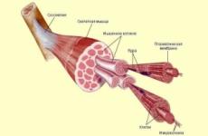
The combustion process is based on chemical reactions Compounds of fuel with oxidizing agent. To leak the process of burning gas must be created special conditions. First, it is necessary to bring the oxidizing agent to the fuel gas in sufficient quantity (most often air) and mix them. Secondly, the gas-air mixture should have concentration limits flammability and should be created a source of ignition. Thirdly, it is necessary to create conditions for the development of the combustion process, i.e., a certain temperature level.
Mixing formation (uniform gas mixing with air) is one of the main stages of the entire combustion process. From the process of mixing formation, all further stages are largely dependent, through which fuel passes when the chemical energy turns into thermal. Since the combustion zone always establishes a high temperature level, the time spent on chemical combustion reactions is always significantly less than the time required for the mixing process.
Burning gas fuel, like any other, in air flow in accordance with modern views is possible on the basis of kinetic and diffusion principles.
The total combustion time of gas, determining the combustion rate,
TP TS ~ 1 "~ x1
Where the TC is the mixing time required to mix the gas with an oxidizing agent; TX - the time of flow of chemical reactions.
If TC<Стх, то практически тп«т*. В этом случае процесс протекает в кинетической области. Если же, наоборот, Тс^-Тх, то Тп»тс и, следовательно, процесс протекает в диффузионной области.
When the combustion process flows in the kinetic region, the combustion rate depends on the properties of this combustible mixture, the temperature in the reaction volume and the concentration of reagents in the burning zone, i.e., is regulated by the laws of chemical kinetics. At the same time, the process rate in the kinetic region does not depend on hydrodynamic factors, i.e. from the flow rate, the geometric dimensions of the reaction chamber, etc.
On the contrary, in the diffusion region, the process rate is determined by hydrodynamic factors and does not depend on the kinetic. In this area, they cease to play the defining role of the properties of a combustible mixture and the temperature factor. Comparatively about so-in-hydrodynamic means can be affected by the mixing intensity, which will lead to a change in the characteristics of the diffusion torch.
With the kinetic principle, a homogeneous gas-air mixture is predetermined in the burner, which is supplied to the fiber chamber. Therefore, the combustion of such a mixture flows with a constant value of all the main characteristics (heat change, excess air, etc.). Pure kinetic combustion occurs only when compliance with the condition A ^ 1.0. With A.<1 кинетическое горение протекает лишь на первой стадии, т. е. до тех пор, пока не израсходован весь кислород смеси. Остаток горючих компонентов, разбавленных продуктами сгорания, может быть сожжен только при условии подвода дополнительного окислителя (воздуха).
The diffusion principle of burning implies the creation of such conditions for the occurrence of the process in which the mixture is burning immediately in its very occurrence, i.e., when contacting fuel and oxidizing agent in the corresponding quantitative ratios. The process of diffusion combustion is regulated by changing the intensity of the mixing formation by varying the structural and mode parameters of the burner. As a result, depending on the technological requirements, it is possible to shorten the mixing zone or its elongation.
In practice, gas combustion is often used, combining both of the principles mentioned. In this case, the portion of the air is pre-mixed with the gas in the burner, and the rest required for complete combustion is supplied directly to the combustion zone. By changing this ratio, you can affect the length of the gas torch. In most burners, the gas is fed under one or another angle to the air flow.
The study of the process of mixing is devoted to a lot of work. This allows you to formulate some common patterns.
For direct-flow gas burners, the mixture is better, the greater part of the cross section of the burner cover gas jets, that is, the greater the range of gas jets. In burners with highly twisted streams should not strive for a large range of gas jets.
An increase in the stream of air flow leads to a redistribution of gas and air over a burner cross section, an increase in the intensity of the mixing of gas with air and an increase in the central zone of reverse currents in the burner.
The nature of the effect of the cooler of the air flow on the mixing process is varied depending on the remaining determining parameters. So, when the gas is submitted to the peripheral zones of the burner (regardless of its type), an increase in the flow curler leads to a noticeable improvement in the mixture formation. On the contrary, when the gas is submitted to the central zone of the burner, the growth of the twist does not lead to an improvement in the process, "solutions.
The set of phenomena, which we call the burning, can only flow in a certain sequence, from one stage to another. G. F. Knorre gives the following schemes of the established process of combustion of gas and liquid fuel with a fixed focus, which it calls in the flow (Fig. 1). The simplest streaming scheme occurs when burning gas fuels consisting of simple molecules (for example, hydrogen), which do not require pre-complex pyrogenic decomposition (Fig. 1, BUT).When gas or liquid hydrocarbon fuel is burned, A 6.
The flow of combustion is complicated: another intermediate stage occurs - the pyrogenic decomposition. For liquid fuels of this stage, the stage of evaporation is preceded (Fig. 1.6). For the implementation of the stream, a sufficient temperature level is needed in a focus of burning, to which the fuel and oxidizer are bodied by continuous threads. Combustion products after the completion of the reactions are also continuously discharged from the burning center.
It is known that gas-air mixtures are flammable only when the gas content in the air is in certain (for each gas) limits. With minor gas content, the amount of heat released during combustion is not enough to bring the adjacent layers of the mixture to the ignition temperature. The same is observed with too much gas content in the gas-air mixture. The lack of air oxygen going on burning leads to a decrease in the temperature level, as a result of which the adjacent layers of the mixture are not heated to
Inflammation temperature. These two cases correspond to the lower and upper limits of flammability (Table 1). Therefore, in addition to mixing gas with air in certain proportions, initial conditions must be created to ignite the mixture.
|
Table / Limits of flammability and temperature of ignition of various gases in the air
|
The oxidation of combustible gases is possible at low temperatures, but then it proceeds extremely slow due to a minor reaction rate. With increasing temperature, the rate of oxidation reaction increases before the onset of self-ignition (instead of slow oxidation, the process of spontaneous combustion begins). It means that the combustible mixture is heated to the ignition temperature, it has such an energy that not only compensates for heat loss into the environment, but provides heating and preparation of a gas-air mixture coming to the combustion zone, to ignition.
The gas ignition temperature depends on a number of factors, including the content of combustible gas in the gas-high-mixture, pressure, the method of heating the mixture, etc., and therefore is not an accurate value. In tab. 1 shows the values \u200b\u200bof the temperature of the ignition of some combustible gases in the air.
In practice, there are two ways to ignite combustible mixtures: self-ignition and ignition.
For Self-ignition The entire volume of the combustible gas-air mixture is gradually communicated to the ignition temperature, after which the mixture is flammable without external thermal exposure.
The technique is widely used by the second method, called Ignition. At the same time, the method is not required to heat the entire gas-air mixture to the ignition temperature, it is enough to light the cold mixture at one point of the volume with some high-temperature source (spark, a rolled body, duty flame, etc.). As a result, ignition is transmitted to the entire volume of the mixture spontaneously by the spread of the flame, which is not instant, and at a certain spatial speed. This speed is called Flame spread rate In the gas-air mixture and is an essential characteristic that determines the conditions for the flow and stabilization of combustion. The stability of the burner work, as will be shown below, is associated with the rate of flame distribution.
Thus, the gas fuel combustion process consists of mixing the gas with air, heating the mixture of the mixture to the ignition temperature, the ignition and the flow of combustion reactions, accompanied by heat release. Moreover, the mixing of the gas with air and the heating of the mixture takes most of the time in the process of burning, since the burning reactions proceed almost instantly.
Depending on the technological process (the preparation of steam and hot water in the boiler unit, the heating of products in the furnace installation, etc.) there is a need to influence the combustion process, changing its final characteristics. This is achieved by various constructive techniques that are set forth in ch. III.
Animally comparison of temperature fields in the volume of the torch when burning gas with different air excess coefficients. An example of such a comparison is given in Fig. 2 for the burner with a 35 mm outlet diameter in the form of dependence
|
|
Where AND - the current temperature value in the torch, ° C; £ tah - the maximum temperature in the flare (measured), ° C; H.- distance from the point of measurement before the start of the torch, m; W. - distance from the point of measurement to the axis of the torch, m; J. - diameter nozzle burner, m.
In fig. 2 shows the temperature distribution graphs for the three air excess coefficients. Moreover, the coordinate X / J.\u003d O corresponds to the output section of the burner nozzle, and the coordinate Y / y\u003d 0 - torch axis.
As can be seen from the drawing, the temperature distribution in the free torch is unevenly. With small excess of primary air, for example, a \u003d 0.5, the presence of an inner core in a torch strongly distorts the temperature field and it is aligned only at a distance x / s / \u003d 10, while at a \u003d 0.75, the alignment occurs already when X / J.\u003d 2.5, and at a \u003d 1.0 even earlier - when X / y \u003d 1.0.
The highest temperatures in open torches are observed in the initial sections at a distance from the torch axis Y / y \u003d0.5, and then in the center of the torch. Moreover, with an increase in the excess air coefficient, maximum temperatures shifts to the mouth of the burner. So, the highest temperature at a \u003d 0.75 is measured at a distance X / J.\u003d 2.5, and at a \u003d 1.0 - at a distance X / y \u003d 1.0.
 With the joint consideration of the temperature distribution and concentrations of C02 in a torch, the maximum coincidence is observed
Temperatures and content C02. Consequently, the maximum temperature level in the torch corresponds to the maximum magnitude of the burnout of flammable.
The losses of the heat part highlighting the combustion of gas are inevitable. However, they can be reduced to a minimum with the proper joker. Consider from what. The constituents fold these losses.
When burning gas fuels, the following heat loss takes place: with outgoing gases, from chemical incompleteness of combustion and in the environment. Based on the definition of individual heat losses on the reverse balance, it may be calculated to. P. D (efficient efficiency) of the unit, ° / о:
Where<72 - потери тепла с уходящими газами, %; - потери тепла
From chemical incompleteness of combustion,%; Q5. - Loss of heat into the environment,%.
Heat loss with outgoing gases - Physical heat of combustion products leaving the unit, are the main. It is impossible to completely eliminate them, but it is necessary to strive to decrease. Heat losses with outgoing gases depend on the temperature of the gases and their quantity. The lower the temperature of the outgoing gases, the smaller the heat will be lost, therefore it should be striving for a decrease in the reasonable limits of the temperature of the outgoing gases. The effect of flowing gases on heat loss is seen from the table. 2.
table 2
|
Heat loss with outgoing gases when burning natural gas,%
|
The weight loss with outgoing gases is usually expressed as a percentage of all disposable heat, that is, from the heat of combustion of fuel. For example, if heat loss is 700 kcal / m3 when burning natural gas, then
700-100 ___ "24 ° /
The amount of gases leaving aggregate depends on the coefficient of excess air, with which the burner works, and sucks
Air through looseness in the unit. The larger the air excess factor at the exit of the burner and air supplies to the unit, the higher the heat loss with exhaust gases. From table. 2 It can be seen that the change in the overall excess air coefficient in combustion products with AA \u003d 1.2-5-1.6 increases the heat loss with outgoing gases from 10.5 to 13.2% (with a continued flowing gases 240 ° C).
Thus, to reduce heat losses with outgoing gases, it is necessary to carry out the combustion process with the smallest permissible oil excess coefficient, ensure the largest density of the unit and to reduce the temperature of the outgoing gases.
Heat losses from the chemical incompleteness of gas combustion occurs with a lack of air, poor mixing in the gas burner, with a sharp decrease in the temperature level in the burning zone. As a result, gas burning proceeds incompletely and combustible components (for example, hydrogen, carbon monoxide, etc.) leave with combustion products. This leads to short-use of the chemical energy of fuel and reduce the efficiency of the aggregate. Even a small content of combustible components in combustion products leads to significant heat loss from the chemical non-payment of combustion. Suppose that in combustion products contained 0.7% hydrogen and 0.5% carbon monoxide. Natural gas was burned in the unit with an excess air coefficient for installation A "\u003d 1.5. The heat loss from the chemical non-payment of combustion was ~ 450 kcal / m3 or
A ___ 450-100 Po /
Thus, from the considered example, it can be seen that combustible components in combustion products must fully have a minimal value.
Heat losses in the environment are related to the fact that the walls of the unit have a higher temperature than the air surrounding it. The magnitude of these losses depends mainly on the temperature difference between the outer walls of the unit and the ambient air, the size of the wall surface, the thermal conductivity of the material of the masonry and its thickness. Environmental losses are calculated theoretically or taken from the norms of thermal calculation depending on the design and productivity of the unit.
If you summarize all the thermal losses that take place when burning gas in the unit, and will subtract them out of 100, then we get to. N. Aggregate. For example, we use the numbers shown above by accepting<75 равным 3,60%, тогда к. п. д. агрегата
T] \u003d 100- (8.24 + 5.28 + 3,60) \u003d 82.88% *
8.1. Reactions burning
G O R E N E - the high-flowing chemical reaction of compounds of combustible components with oxygen, accompanied by intensive heat release and sharp increase in the temperature of combustion products. The combustion reactions are described by the so-called. Stoichiometric equations characterizing qualitatively and quantitatively reacting and resulting from its substance (The stoichiometric composition of the combustible mixture (from Greek. Stoicheion is the base, element and Greek. Metreo - I measure) - the composition of the mixture in which the oxidizer is exactly as much as necessary for complete oxidation of the fuel). General equation of the combustion of any hydrocarbon
C M H n + (M + N / 4) O 2 \u003d MCO 2 + (N / 2) H 2 O + Q (8.1)
where m, n is the number of carbon and hydrogen atoms in the molecule; Q is the thermal effect of the reaction, or heat of combustion.
The combustion reactions of some gases are shown in Table. 8.1. These equations are balanced, and it is impossible to judge the speed of reactions or the mechanism of chemical transformations.
Table 8.1. The combustion reactions and heat combustion of dry gases (at 0 ° C and 101.3 kPa)
| Gas | The reaction of burning | Heat combustion | |||||
|---|---|---|---|---|---|---|---|
| Molar, kj / kmol | Mass, kJ / kg | Volumenny, kj / m 3 | |||||
| higher | lost | higher | lost | higher | lost | ||
| Hydrogen | H 2 + 0.5O 2 \u003d H 2 0 | 286,06 | 242,90 | 141 900 | 120 080 | 12 750 | 10 790 |
| Carbon oxide | CO + 0.5O 2 \u003d CO 2 | 283,17 | 283,17 | 10 090 | 10 090 | 12 640 | 12 640 |
| Methane | CH 4 + 2O 2 \u003d CO 2 + 2H 2 O | 880,90 | 800,90 | 55 546 | 49 933 | 39 820 | 35 880 |
| Ethane | C 2 H 6 + 0.5O 2 \u003d 2CO 2 + 3H 2 O | 1560,90 | 1425,70 | 52 019 | 47 415 | 70 310 | 64 360 |
| Propane | C 3 H 8 + 5H 2 O \u003d 3CO 2 + 4H 2 O | 2221,40 | 2041,40 | 50 385 | 46 302 | 101 210 | 93 180 |
| n-buthin | 2880,40 | 2655,00 | 51 344 | 47 327 | 133 800 | 123 570 | |
| Isobutan | C 4 H 10 + 6,5O 2 \u003d 4CO 2 + 5H 2 O | 2873,50 | 2648,30 | 51 222 | 47 208 | 132 960 | 122 780 |
| n-pentan | C 5 H 12 + 8O 2 \u003d 5CO 2 + 6H 2 O | 3539,10 | 3274,40 | 49 052 | 45 383 | 169 270 | 156 630 |
| Ethylene | C 2 H 4 + 3O 2 \u003d 2CO 2 + 2H 2 O | 1412,00 | 1333,50 | 50 341 | 47 540 | 63 039 | 59 532 |
| Propylene | C 3 H 6 + 4,5O 2 \u003d 3CO 2 + 3H 2 O | 2059,50 | 1937,40 | 48 944 | 46 042 | 91 945 | 88 493 |
| Boutylene | C 4 H 8 + 6O 2 \u003d 4CO 2 + 4H 2 O | 2720,00 | 2549,70 | 48 487 | 45 450 | 121 434 | 113 830 |
The t e n o v o e f ф e to (heat of combustion) q is the amount of heat released in full combustion of 1 km, 1 kg or 1 m 3 of gas under normal physical conditions. The highest q c and lower q n heat of combustion: the highest heat of the combustion includes the heat of condensation of water vapor in the process of burning (in reality when burning gas, water vapors are not condensed, but are removed along with other combustion products). Typically, technical calculations usually lead along the lowest heat of combustion, without taking into account the heat of the condensation of water vapor (≈ 2400 kJ / kg).
The efficiency, calculated on the lowest heat of combustion, is formally higher, but the heat of the condensation of water vapors is large enough, and its use is more than appropriate. Confirmation of this is an active application in the heating technique of contact heat exchangers, very diverse in design.
For a mixture of combustible gases, the highest (and lower) heat combustion of gases is determined by the ratio
Q \u003d R 1 Q 1 + R 2 Q 2 + ... + R n q n (8.2)
where R 1, R 2, ..., R n is bulk (molar, massive) fraction of components included in the mixture; Q 1, q 2, ..., q n - heat combustion of components.
Taking advantage of the table. 8.1, the highest and lower heat of combustion, KJ / m 3, complex gas can be determined by the following formulas:
Q \u003d 127.5 H 2 + 126.4 C + 398 CH 4 + 703 C 2 H 6 + 1012 C 8 H 8 + 1338 C 4 H 10 + 1329 C 4 H 10 +
+ 1693 C 5 H 12 + 630 C 2 H 4 + 919 C 3 H 6 +1214 C 4 H 8 (8.3)
Q H \u003d 107.9 H 2 + 126.4 CO + 358,8 CH 4 + 643 C 2 H 6 + 931.8 C 8 H 8 + 1235 C 4 H 10 + 1227 C 4 H 10 +
+ 1566 C 5 H 12 + 595 C 2 H 4 + 884 C 8 H 6 + 1138 C 4 H 8 (8.4)
where H 2, CO, CH 4, etc. - The content of individual components in gas fuel, about. %.
The combustion process proceeds much more difficult than according to formula (8.1), since along with the branching of the chains, they are broken by the formation of intermediate stable compounds, which at high temperatures undergo further conversion. With a sufficient oxygen concentration, final products are formed: water vapor N 2 o and carbon dioxide CO 2. With a lack of oxidizing agent, as well as when cooled by the reaction zone, intermediate connections can stabilize and enter the environment.
The heat generation intensity and temperature rise leads to an increase in the active particle reacting system. Such interrelation of chain response and temperature peculiar to almost all combustion processes has led to the introduction of the concept of the chain-thermal explosion - the chemical combustion reactions themselves have a chain character, and their acceleration occurs due to the release of heat and temperature growth in the reacting system.
The rate of chemical reaction in a homogeneous mixture is proportional to the product of the concentrations of the reactant substances:
w \u003d kc 1 C 2 (8.5)
where C 1 and C 2 is the concentration of reacting components, kmol / m 3; k is a reaction rate constant, depending on the nature of the reacting substances and temperature.
When burning the gas concentration of reactants can be considered unchanged, since in the burning zone there is a continuous influx of fresh components of the unambiguous composition.
Reaction rate constant (according to the Arrhenius equation):
K \u003d K 0 E -E / RT (8.6)
where K 0 is a pre-exponential factor taken for biometric homogeneous mixtures, ≈1.0; E - activation energy, kJ / kmol; R is a universal gas constant, J / (kg to); T - absolute temperature, to (° C); E is the basis of natural logarithms.
The pre-exponential factor to 0 can be interpreted as a constant reflecting the completeness of the collision of molecules, and E - as the minimum energy of the bonding bonds of molecules and the formation of active particles that ensure the effectiveness of collisions. For common combustible mixtures, it stacked within (80 ÷ 150) 10 3 kJ / kmol.
Equation (8.6) indicates that the rate of chemical reactions increases sharply with increasing temperature: for example, an increase in the temperature from 500 to 1000 to the increase in the rate of combustion reaction at 2 10 4 ÷ 5 10 8 times (depending on the activation energy).
The rate of combustion reactions affects their chain character. The initially generated atoms and radicals enter into compounds with the source substances and together, forming finite products and new particles repeating the same chain of reactions. The growing generation of such particles leads to "acceleration" of chemical reactions - in fact exploding the entire mixture.
High-temperature combustion of hydrocarbons is complex and is associated with the formation of active particles in the form of atoms and radicals, as well as intermediate molecular compounds. As an example, the combustion reactions of the simplest hydrocarbon - methane are given:
- N + O 2 -\u003e He + O
CH 4 + it -\u003e CH 3 + H 2 O
CH 4 + O -\u003e CH 2 + N 2 O - CH 3 + O 2 -\u003e NSNO + he
CH 2 + O 2 -\u003e NSNO + O - Nso + he -\u003e NSO + N 2
NNO + O -\u003e CO + N 2 O
NSO + O 2 -\u003e CO + O + - CO + O -\u003e CO 2
CO + it -\u003e CO 2 + N
The outcome of the unit cycle:
2SH 4 + 4O 2 -\u003e 2 + 2 + 4N 2
8.2. Calculations of burning
Oxygen for combustion comes from air as its component. For calculations, it is assumed that the volumetric composition of dry air is as follows:
oxygen - 21.0%, nitrogen - 79.0%.
According to the information provided, 1 m 3 of oxygen is contained in 100/21 \u003d 4.76 m 3 of air, or 1 m 3 of oxygen accounts for 79/21 \u003d 3.76 m 3 of nitrogen. Given that 1 kmol gas under normal conditions occupies a capacity of 22.4 liters, the combustion reaction (see Equation 8.1) of any hydrocarbon in the air can be written in a generalized form:
C M H n + (T + N / 4) (O 2 + 3.76N 2) \u003d TCO 2 + (N / 2) H 2 O + (T + N / 4) 3.76N 2
The needs for oxygen and air during the burning of various gases, counted according to the above combustion reactions, are presented in Table. 8.2.
Table 8.2. Theoretical need for dry oxygen and air, m 3, and the volume of gas combustion products when burning 1 m 3 gas
| Gas | Theoretical need | Products of combustion | ||||
|---|---|---|---|---|---|---|
| oxygen | air | carbon dioxide | water par | nitrogen | total | |
| Hydrogen H 2. | 0,5 | 2,38 | – | 1,0 | 1,88 | 2,88 |
| Carbon Oxide Co. | 0,5 | 2,38 | 1,0 | – | 1,88 | 2,88 |
| Methane CH 4. | 2,0 | 9,52 | 1,0 | 2,0 | 7,52 | 10,52 |
| Ethan C 2 H 6 | 3,5 | 16,66 | 2,0 | 3,0 | 13,16 | 18,16 |
| Propane C 3 H 8 | 5,0 | 23,80 | 3,0 | 4,0 | 18,80 | 25,80 |
| Butane C 4 H 10 | 6,5 | 30,94 | 4,0 | 5,0 | 24,44 | 33,44 |
| Pentane C 5 H 12 | 8,0 | 38,08 | 5,0 | 6,0 | 30,08 | 41,08 |
| Ethylene C 2 H 4 | 3,0 | 14,28 | 2,0 | 2,0 | 11,28 | 15,28 |
| Propylene C 3 H 6 | 4,5 | 21,42 | 3,0 | 3,0 | 16,92 | 22,92 |
| Boutylene C 4 H 8 | 6,0 | 28,56 | 4,0 | 4,0 | 22,56 | 30,56 |
| Pentylene C 5 H 10 | 7,5 | 35,70 | 5,0 | 5,0 | 28,20 | 38,20 |
| Acetylene C 2 H 2 | 2,5 | 11,90 | 2,0 | 1,0 | 9,40 | 12,40 |
For complex gas, dry air consumption V C, M 3 / m 3 is calculated by the formula that takes into account the need for the oxygen of individual components of the mixture:
V C \u003d 4.76 / 100 (0.5N 2 + 0.5CH + 2SH 4 + 3.5C 2 H 6 + 5C 3 H 8 + 6.5C 4 H 10 + 3C 2N 4 + 4,5C 3N 6 + 6C 4 H 8 -O 2) (8.7)
Theoretical consumption of wet air V VL, M 3 / m 3, more determined by formula (8.7) on the volume of water vapor contained:
V Vl \u003d V C + 0.001244D in V C (8.8)
where D is the humidity of the air, g / m 3.
With an unknown chemical composition of gases, but the well-known lower heat of the combustion of Q H, KJ / M 3, the theoretical consumption of air V T, M 3 / m 3,
V T ≈ Q n /3770(8.9)
The real air consumption V DV, M 3 / m 3, is always taken somewhat large:
V DV \u003d V T α (8.10)
where α is an excess air coefficient corresponding to the requirements of GOST. For complete combustion of the fuel, the value of α must be more than 1. The composition and volume of combustion products, calculated by the combustion reactions of some gases in dry air, is given in Table. 8.2.
8.3. Combustion temperature
In the heat engineering, the following gas combustion temperatures differ: heat-producing, calorimetric, theoretical and valid (calculated). Heat productivity T f - the maximum temperature of the total combustion of gas in adiabatic conditions with an excess air coefficient α \u003d 1.0 and at a gas and air temperature equal to 0 ° C:
t w \u003d Q n / (σvc p) (8.11)
where q n is the lowest heat combustion heat, KJ / m 3; Σvc p - the amount of products of carbon dioxide volumes, water vapor and nitrogen formed during combustion of 1 m 3 of gas (m 3 / m 3), and their average volumetric heat capacity at a constant pressure within temperatures from 0 ° C to T g (kJ / (m 3 O ° C).
By virtue of the inconstancy of the heat capacity of gases, heat produce is determined by the method of consecutive approximations. It takes its value for natural gas (≈ 2000 ° C) as the initial parameter, with α \u003d 1.0, the volume of components of combustion products are determined, in Table. 8.3 There is their average heat capacity and then according to formula (8.11), the heat production capacity is considered. If as a result of counting it will be lower or higher, then another temperature is specified and the calculation is repeated.
Table 8.3. Average volumetric heat capacity of gases, kJ / (m 3 ° С)
Temperature, ° С |
CO 2. | N 2. | O 2. | Co. | CH 4. | H 2. | H 2 O (Water Couples) | air | |
|---|---|---|---|---|---|---|---|---|---|
| dry | wet on 1 m 3 suh Gas. |
||||||||
| 0 | 1,5981 | 1,2970 | 1,3087 | 1,3062 | 1,5708 | 1,2852 | 1,4990 | 1,2991 | 1,3230 |
| 100 | 1,7186 | 1,2991 | 1,3209 | 1,3062 | 1,6590 | 1,2978 | 1,5103 | 1,3045 | 1,3285 |
| 200 | 1,8018 | 1,3045 | 1,3398 | 1,3146 | 1,7724 | 1,3020 | 1,5267 | 1,3142 | 1,3360 |
| 300 | 1,8770 | 1,3112 | 1,3608 | 1,3230 | 1,8984 | 1,3062 | 1,5473 | 1,3217 | 1,3465 |
| 400 | 1,9858 | 1,3213 | 1,3822 | 1,3356 | 2,0286 | 1,3104 | 1,5704 | 1,3335 | 1,3587 |
| 500 | 2,0030 | 1,3327 | 1,4024 | 1,3482 | 2,1504 | 1,3104 | 1,5943 | 1,3469 | 1,3787 |
| 600 | 2,0559 | 1,3453 | 1,4217 | 1,3650 | 2,2764 | 1,3146 | 1,6195 | 1,3612 | 1,3873 |
| 700 | 2,1034 | 1,3587 | 1,3549 | 1,3776 | 2,3898 | 1,3188 | 1,6464 | 1,3755 | 1,4020 |
| 800 | 2,1462 | 1,3717 | 1,4549 | 1,3944 | 2,5032 | 1,3230 | 1,6737 | 1,3889 | 1,4158 |
| 900 | 2,1857 | 1,3857 | 1,4692 | 1,4070 | 2,6040 | 1,3314 | 1,7010 | 1,4020 | 1,4293 |
| 1000 | 2,2210 | 1,3965 | 1,4822 | 1,4196 | 2,7048 | 1,3356 | 1,7283 | 1,4141 | 1,4419 |
| 1100 | 2,2525 | 1,4087 | 1,4902 | 1,4322 | 2,7930 | 1,3398 | 1,7556 | 1,4263 | 1,4545 |
| 1200 | 2,2819 | 1,4196 | 1,5063 | 1,4448 | 2,8812 | 1,3482 | 1,7825 | 1,4372 | 1,4658 |
| 1300 | 2,3079 | 1,4305 | 1,5154 | 1,4532 | – | 1,3566 | 1,8085 | 1,4482 | 1,4771 |
| 1400 | 2,3323 | 1,4406 | 1,5250 | 1,4658 | – | 1,3650 | 1,8341 | 1,4582 | 1,4876 |
| 1500 | 2,3545 | 1,4503 | 1,5343 | 1,4742 | – | 1,3818 | 1,8585 | 1,4675 | 1,4973 |
| 1600 | 2,3751 | 1,4587 | 1,5427 | – | – | – | 1,8824 | 1,4763 | 1,5065 |
| 1700 | 2,3944 | 1,4671 | 1,5511 | – | – | – | 1,9055 | 1,4843 | 1,5149 |
| 1800 | 2,4125 | 1,4746 | 1,5590 | – | – | – | 1,9278 | 1,4918 | 1,5225 |
| 1900 | 2,4289 | 1,4822 | 1,5666 | – | – | – | 1,9698 | 1,4994 | 1,5305 |
| 2000 | 2,4494 | 1,4889 | 1,5737 | 1,5078 | – | – | 1,9694 | 1,5376 | 1,5376 |
| 2100 | 2,4591 | 1,4952 | 1,5809 | – | – | – | 1,9891 | – | – |
| 2200 | 2,4725 | 1,5011 | 1,5943 | – | – | – | 2,0252 | – | – |
| 2300 | 2,4860 | 1,5070 | 1,5943 | – | – | – | 2,0252 | – | – |
| 2400 | 2,4977 | 1,5166 | 1,6002 | – | – | – | 2,0389 | – | – |
| 2500 | 2,5091 | 1,5175 | 1,6045 | – | – | – | 2,0593 | – | – |
The heat-produceness of common simple and complex gases during their combustion in dry air is given in Table. 8.4. When burning gas in atmospheric air, containing about 1 weight. % moisture, heat production capacity is reduced by 25-30 ° C.
Table 8.4. Gas heat production capacity in dry air
| Simple gas | Heat productivity, ° С | Sophisticated gas averaged composition |
Approximate heat efficiency, ° С |
|---|---|---|---|
| Hydrogen | 2235 | Natural gas deposits |
2040 |
| Carbon oxide | 2370 | Natural oil fields |
2080 |
| Methane | 2043 | Coke |
2120 |
| Ethane | 2097 | High temperature distillation shale |
1980 |
| Propane | 2110 | Paroxogeneous pressure under pressure |
2050 |
| Butane | 2118 | Solid coal generator |
1750 |
| Pentane | 2119 | Slesting fuel generator |
1670 |
| Ethylene | 2284 | Liquefied (50% C 3 H 4 + 50% C 4 H 10) |
2115 |
| Acetylene | 2620 | 2210 |
Calorimetric combustion temperature T K is the temperature determined without taking into account the dissociation of water vapor and carbon dioxide, but taking into account the actual initial gas and air temperature. It differs from heat-producing t w in the fact that the temperature of the gas and air, as well as the air coefficient α is accepted according to their valid values. Determine T K by the formula:
t K \u003d (Q H + Q FIZ) / (ΣVC P) (8.12)
where q Piz - heat-containing (physical heat) of gas and air, counted from 0 ° C, KJ / m 3.
Natural and liquefied hydrocarbon gases are usually not heated before burning, and their volume compared with the volume of air coming to burning is small. Therefore, when determining calorimetric temperatures, the heat generation of gases can not be considered. When burning gases with low heat of combustion (generator, domain, etc.), their heat generation (especially heated prior to combustion) has a very significant effect on the calorimetric temperature.
The dependence of the calorimetric temperature of the natural gas of the average composition in air with a temperature of 0 ° C and a humidity of 1% of the air excess coefficient α is given in Table. 8.5, for liquefied hydrocarbon gas when it burns in dry air - in Table. 8.7. Data table. 8.5-8.7 can be guided with sufficient accuracy when establishing a calorimetric temperature of combustion of other natural gases, relatively close in composition, and hydrocarbon gases of virtually any composition. If necessary, to obtain a high temperature when burning gases with low air excess coefficients, as well as to increase the efficiency of the furnaces, air is heated in practice, which leads to an increase in calorimetric temperature (see Table 8.6).
Table 8.5. Calorimetric and theoretical temperature of burning natural gas in the air with T \u003d 0 ° C and a humidity of 1% depending on the excess air coefficient α
| Theoretical combustion temperature T T, ° C | Air excess coefficient α | Calorimetric combustion temperature T to, ° C | ||
|---|---|---|---|---|
| 1,0 | 2010 | 1920 | 1,33 | 1620 |
| 1,02 | 1990 | 1900 | 1,36 | 1600 |
| 1,03 | 1970 | 1880 | 1,40 | 1570 |
| 1,05 | 1940 | 1870 | 1,43 | 1540 |
| 1,06 | 1920 | 1860 | 1,46 | 1510 |
| 1,08 | 1900 | 1850 | 1,50 | 1470 |
| 1,10 | 1880 | 1840 | 1,53 | 1440 |
| 1,12 | 1850 | 1820 | 1,57 | 1410 |
| 1,14 | 1820 | 1790 | 1,61 | 1380 |
| 1,16 | 1800 | 1770 | 1,66 | 1350 |
| 1,18 | 1780 | 1760 | 1,71 | 1320 |
| 1,20 | 1760 | 1750 | 1,76 | 1290 |
| 1,22 | 1730 | – | 1,82 | 1260 |
| 1,25 | 1700 | – | 1,87 | 1230 |
| 1,28 | 1670 | – | 1,94 | 1200 |
| 1,30 | 1650 | – | 2,00 | 1170 |
Table 8.6. The calorimetric temperature of the burning of natural gas T to, ° C, depending on the coefficient of excess of dry air and its temperature (rounded values)
| Air excess coefficient α | Dry air temperature, ° C | ||||||||
|---|---|---|---|---|---|---|---|---|---|
| 20 | 100 | 200 | 300 | 400 | 500 | 600 | 700 | 800 | |
| 0,5 | 1380 | 1430 | 1500 | 1545 | 1680 | 1680 | 1740 | 1810 | 1860 |
| 0,6 | 1610 | 1650 | 1715 | 1780 | 1840 | 1900 | 1960 | 2015 | 2150 |
| 0,7 | 1730 | 1780 | 1840 | 1915 | 1970 | 2040 | 2100 | 2200 | 2250 |
| 0,8 | 1880 | 1940 | 2010 | 2060 | 2130 | 2200 | 2260 | 2330 | 2390 |
| 0,9 | 1980 | 2030 | 2090 | 2150 | 2220 | 2290 | 2360 | 2420 | 2500 |
| 1,0 | 2050 | 2120 | 2200 | 2250 | 2320 | 2385 | 2450 | 2510 | 2560 |
| 1,2 | 1810 | 1860 | 1930 | 2000 | 2070 | 2140 | 2200 | 2280 | 2350 |
| 1,4 | 1610 | 1660 | 1740 | 1800 | 2870 | 1950 | 2030 | 2100 | 2160 |
| 1,6 | 1450 | 1510 | 1560 | 1640 | 1730 | 1800 | 1860 | 1950 | 2030 |
| 1,8 | 1320 | 1370 | 1460 | 1520 | 1590 | 1670 | 1740 | 1830 | 1920 |
| 2,0 | 1220 | 1270 | 1360 | 1420 | 1490 | 1570 | 1640 | 1720 | 1820 |
Table 8.7. Calorimetric combustion temperature T to technical propane in dry air with t \u003d 0 ° C, depending on the excess air coefficient α
| Air excess coefficient α | Calorimetric combustion temperature T to, ° C | Air excess coefficient α | Calorimetric combustion temperature T to, ° C |
|---|---|---|---|
| 1,0 | 2110 | 1,45 | 1580 |
| 1,02 | 2080 | 1,48 | 1560 |
| 1,04 | 2050 | 1,50 | 1540 |
| 1,05 | 2030 | 1,55 | 1500 |
| 1,07 | 2010 | 1,60 | 1470 |
| 1,10 | 1970 | 1,65 | 1430 |
| 1,12 | 1950 | 1,70 | 1390 |
| 1,15 | 1910 | 1,75 | 1360 |
| 1,20 | 1840 | 1,80 | 1340 |
| 1,25 | 1780 | 1,85 | 1300 |
| 1,27 | 1750 | 1,90 | 1270 |
| 1,30 | 1730 | 1,95 | 1240 |
| 1,35 | 1670 | 2,00 | 1210 |
| 1,40 | 1630 | 2,10 | 1170 |
Theoretical combustion temperature T T - the maximum temperature determined similarly to the calorimetric T K, but with amendment to endothermic (requiring heat) of the dissociation of carbon dioxide dioxide and water steam, going with an increase in volume:
CO 2 \u003c-\u003e CO + 0.5O 2 - 283 MJ / Mol (8.13)
H 2 O \u003c-\u003e H 2 + 0.5O 2 - 242 MJ / Mol (8.14)
At high temperatures, dissociation can lead to the formation of atomic hydrogen, oxygen and hydroxyl groups. In addition, when burning gas, a certain amount of nitrogen oxide is always formed. All these reactions are endothermichny and lead to a decrease in combustion temperature.
Theoretical combustion temperature can be determined by the following formula:
t T \u003d (Q H + Q Piz - Q Dis) / (ΣVC P) (8.15)
where Q dis is the total cost of heat for dissociation CO 2 and H 2 O in combustion products, KJ / m 3; Σvc p - the sum of the volume of the volume and the average heat capacity of combustion products, taking into account the dissociation by 1 m 3 of gas.
Table 8.8. The degree of dissociation of water vapor H 2 O and carbon dioxide CO 2 depending on the partial pressure
| Temperature, ° С | Partial pressure, MPa | |||||||||||
|---|---|---|---|---|---|---|---|---|---|---|---|---|
| 0,004 | 0,006 | 0,008 | 0,010 | 0,012 | 0,014 | 0,016 | 0,018 | 0,020 | 0,025 | 0,030 | 0,040 | |
| Water vapor h 2 o | ||||||||||||
| 1600 | 0,85 | 0,75 | 0,65 | 0,60 | 0,58 | 0,56 | 0,54 | 0,52 | 0,50 | 0,48 | 0,46 | 0,42 |
| 1700 | 1,45 | 1,27 | 1,16 | 1,08 | 1,02 | 0,95 | 0,90 | 0,85 | 0,8 | 0,76 | 0,73 | 0,67 |
| 1800 | 2,40 | 2,10 | 1,90 | 1,80 | 1,70 | 1,60 | 1,53 | 1,46 | 1,40 | 1,30 | 1,25 | 1,15 |
| 1900 | 4,05 | 3,60 | 3,25 | 3,0 | 2,85 | 2,70 | 2,65 | 2,50 | 2,40 | 2,20 | 2,10 | 1,9 |
| 2000 | 5,75 | 5,05 | 4,60 | 4,30 | 4,0 | 3,80 | 3,55 | 3,50 | 3,40 | 3,15 | 2,95 | 2,65 |
| 2100 | 8,55 | 7,50 | 6,80 | 6,35 | 6,0 | 5,70 | 5,45 | 5,25 | 5,10 | 4,80 | 4,55 | 4,10 |
| 2200 | 12,3 | 10,8 | 9,90 | 9,90 | 8,80 | 8,35 | 7,95 | 7,65 | 7,40 | 6,90 | 6,50 | 5,90 |
| 2300 | 16,0 | 15,0 | 13,7 | 12,9 | 12,2 | 11,6 | 11,1 | 10,7 | 10,4 | 9,6 | 9,1 | 8,4 |
| 2400 | 22,5 | 20,0 | 18,4 | 17,2 | 16,3 | 15,6 | 15,0 | 14,4 | 13,9 | 13,0 | 12,2 | 11,2 |
| 2500 | 28,5 | 25,6 | 23,5 | 22,1 | 20,9 | 20,0 | 19,3 | 18,6 | 18,0 | 16,8 | 15,9 | 14,6 |
| 3000 | 70,6 | 66,7 | 63,8 | 61,6 | 59,6 | 58,0 | 56,5 | 55,4 | 54,3 | 51,9 | 50,0 | 47,0 |
| CO 2 carbon dioxide | ||||||||||||
| 1500 | 0,5 | 0,5 | 0,5 | 0,5 | 0,5 | 0,5 | 0,4 | 0,4 | 0,4 | 0,4 | 0,4 | – |
| 1600 | 2,0 | 1,8 | 1,6 | 1,5 | 1,45 | 1,4 | 1,35 | 1,3 | 1,25 | 1,2 | 1,1 | |
| 1700 | 3,8 | 3,3 | 3,0 | 2,8 | 2,6 | 2,5 | 2,4 | 2,3 | 2,2 | 2,0 | 1,9 | |
| 1800 | 6,3 | 5,5 | 5,0 | 4,6 | 4,4 | 4,2 | 4,0 | 3,8 | 3,7 | 3,5 | 3,3 | |
| 1900 | 10,1 | 8,9 | 8,1 | 7,6 | 7,2 | 6,8 | 6,5 | 6,3 | 6,1 | 5,6 | 5,3 | |
| 2000 | 16,5 | 14,6 | 13,4 | 12,5 | 11,8 | 11,2 | 10,8 | 10,4 | 10,0 | 9,4 | 8,8 | |
| 2100 | 23,9 | 21,3 | 19,6 | 18,3 | 17,3 | 16,5 | 15,9 | 15,3 | 14,9 | 13,9 | 13,1 | |
| 2200 | 35,1 | 31,5 | 29,2 | 27,5 | 26,1 | 25,0 | 24,1 | 23,3 | 22,6 | 21,2 | 20,1 | |
| 2300 | 44,7 | 40,7 | 37,9 | 35,9 | 34,3 | 32,9 | 31,8 | 30,9 | 30,0 | 28,2 | 26,9 | |
| 2400 | 56,0 | 51,8 | 48,8 | 46,5 | 44,6 | 43,1 | 41,8 | 40,6 | 39,6 | 37,5 | 35,8 | |
| 2500 | 66,3 | 62,2 | 59,3 | 56,9 | 55,0 | 53,4 | 52,0 | 50,7 | 49,7 | 47,3 | 45,4 | |
| 3000 | 94,9 | 93,9 | 93,1 | 92,3 | 91,7 | 90,6 | 90,1 | 89,6 | 88,5 | 87,6 | 86,8 | |
As can be seen from the table. 8.8, at a temperature of up to 1600 ° C, the degree of dissociation may not be taken into account, and the theoretical combustion temperature can be taken equal to calorimetric. At a higher temperature, the degree of dissociation can significantly reduce the temperature in the workspace. In practice, there is no particular need for this, the theoretical combustion temperature must be determined only for high-temperature furnaces operating at a preheated air (for example, Mainens). For boiler plants there are no needs.
Table 8.9. Maximum
temperatures arising
in free flame, ° С
Valid (calculated) temperature of combustion products T d - Temperature that is achieved in real conditions in the hottest point of the torch. It is lower than theoretical and depends on the loss of heat into the environment, the degree of recoil heat from the burning area by radiation, stretching the process of burning over time, etc. The actual averaged temperatures in the furnaces of furnaces and boilers are determined by heat balance or approximately on theoretical or calorimetric combustion temperature depending on From the temperature in the furnaces with the introduction of experimentally installed correction coefficients in them:
t d \u003d t t η (8.16)
where η- Pyrometric coefficient stacked within:
- for high-quality thermal and heating stoves with thermal insulation - 0.75-0.85;
- for hermetic furnaces without heat insulation - 0.70-0.75;
- for shielded floors of boilers - 0.60-0.75.
In practice, not only the above-mentioned adiabatic combustion temperatures, but also the maximum temperatures arising in flames. Their approximate values \u200b\u200bare usually installed experimentally by spectrography methods. The maximum temperatures arising in the free flame at a distance of 5-10 mm from the vertex of the cone front of the combustion are shown in Table. 8.9. The analysis of the given data shows that the maximum temperatures in the flame are less than heat produce (due to the cost of heat on the dissociation of H 2 O and CO 2 and the removal of heat from the flame zone).
8.4. Self-ignion temperature
To initiate combustion reactions, the conditions of ignition of fuel mixture with an oxidizing agent are needed. Inflammation can be spontaneous and forced (ignition).
Self-ignion temperature - The minimum temperature in which spontaneous (i.e. without external heat supply) begins in the heated gas-air mixture), by separating heat by burning gas particles.
The self-ignition temperature is not fixed for this gas and depends on many parameters: its contents in the gas-air mixture, degree of homogeneity of the mixture, shape and size of the vessel, in which the mixture heats up, the speed and method of its heating, the catalytic effect of the vessel wall, pressure under which is located mixture. Accurate accounting of listed factors is very complex, therefore, in practice, for example, when evaluating explosion hazard, use experimental data (see Table 8.10).
Table 8.10. The smallest measured temperatures of self-ignition of some gases and vapors in the air mixture at atmospheric pressure
The temperature of self-ignition combustion gases in oxygen is slightly lower than in the air. The introduction of ballast impurities (nitrogen and carbon dioxide) gases leads to an increase in self-ignition temperature. The presence in complex gases of components with a low temperature of self-ignition leads to a decrease in the temperature of self-ignition of the mixture.
Forced ignition (ignition) is carried out by igniting the mixture in one or in a number of points by a high-temperature source - an open flame or electric spark at the point of gas from the fire channels of the burner in the fuel volume. The ignition differs from self-ignition by the fact that the fuel mixture is brought to the appearance of the flame not all over the volume, but only in a small part of it. The heat sink from the heated zone requires that the heat dissipation intensity of the ignition source exceeds this heat removal. After ignition, the ignition source is removed, and the combustion occurs due to the spread of the flame front.
8.5. Flammability limits and explosions
Gas-high mixtures may ignite (explode) only when the gas content in the mixture is in certain (for each gas) limits. In this regard, the lower and upper concentration limits of flammability are distinguished. The lower limit corresponds to the minimum, and the upper - the maximum amount of gas in the mixture, in which their ignition occurs (when igniting) and spontaneous (without heat intake) the spread of the flame (self-ignition). These limits correspond to the conditions of explosion of gas-air mixtures.
If the gas content in the gas-grade mixture is less than the lower limit of flammability, such a mixture is lit and explode, since the heat of heat released near the source is not enough to heat the mixture to the ignition temperature. If the gas content in the mixture is between the lower and the upper limits of flammability, the proposed mixture is flammable and lit as near the ignition source and when it is removed. This mixture is explosive. The wider there will be a range of flammability limits (also called explosion limits) and below the lower limit, the more explosive gas. And finally, if the gas content in the mixture exceeds the upper limit of flammability, the amount of air in the mixture is not enough for complete combustion of the gas.
The existence of flammability limits is caused by thermal loss during combustion. When diluting a combustible mixture with air, oxygen or gas, thermal losses increase, the flame propagation rate is reduced, and the combustion stops after removing the ignition source.
Table 8.11. Gas flammability limits in a mixture with air (at t \u003d 20 ° C and p \u003d 101.3 kPa)
| Gas | Gas content in a gas-air mixture, about. % | Maximum |
Outlet air coefficient α with ignition limits | ||||
|---|---|---|---|---|---|---|---|
| With the limits of flammability | With stoichiometric composition of the mixture | Under the composition of the mixture that gives the maximum explosion pressure | |||||
| nizhny | upper | nizhny | upper | ||||
| Hydrogen | 4,0 | 75,0 | 29,5 | 32,3 | 0,739 | 9,8 | 0,15 |
| Carbon oxide | 12,5 | 74,0 | 29,5 | – | – | 2,9 | 0,15 |
| Methane | 5,0 | 15,0 | 9,5 | 9,8 | 0,717 | 1,8 | 0,65 |
| Ethane | 3,2 | 12,5 | 5,68 | 6,28 | 0,725 | 1,9 | 0,42 |
| Propane | 2,3 | 9,5 | 4,04 | 4,60 | 0,858 | 1,7 | 0,40 |
| n-buthin | 1,7 | 8,5 | 3,14 | 3,6 | 0,858 | 1,7 | 0,35 |
| Isobutan | 1,8 | 8,4 | 3,14 | – | – | ~1,8 | 0,35 |
| n-pentan | 1,4 | 7,8 | 2,56 | 3,0 | 0,865 | 1,8 | 0,31 |
| Ethylene | 3,0 | 16,0 | 6,5 | 8,0 | 0,886 | 2,2 | 0,17 |
| Propylene | 2,4 | 10,0 | 4,5 | ~5,1 | ~0,89 | 1,9 | 0,37 |
| Boutylene | 1,7 | 9,0 | 3,4 | ~4,0 | ~0,88 | 1,7 | 0,35 |
| Acetylene | 2,5 | 80,0 | 7,75 | 14,5 | 1,03 | 3,3 | 0,019 |
Table 8.12. Gas flammability limits in a mixture with oxygen (at t \u003d 20 ° C and p \u003d 101.3 kPa)
The limits of flammability for common gases in mixtures with air and oxygen are shown in Table. 8.11-8.12. With an increase in the temperature of the mixture, the flammability limits are expanded, and at a temperature greater than the temperature of self-ignition, a mixture of gas with air or oxygen is lit with any bulk ratio.
The limits of flammability depend not only on the types of combustible gases, but also on the conditions for carrying out experiments (vessel capacity, heat source of the ignition source, the temperature of the mixture, the flame propagation up, down, horizontally, etc.). This explains the significance of these limits different from each other in various literary sources. In tab. 8.11-8.12 The relatively reliable data obtained at room temperature and atmospheric pressure when the flame is spread from the bottom up in the tube with a diameter of 50 mm and more. When the flame is spread from top to bottom or horizontally, the lower limits increase slightly, and the upper decreases. The limits of flammability of complex combustible gases that do not contain ballast impurities are determined by the rule of additivity:
L G \u003d (R 1 + R 2 + ... + R n) / (R 1 / L 1 + R 2 / L 2 + ... + R N / L n) (8.17)
where L g is the lower or the upper limit of the flammability of the complex gas in the gas-air or gas particle mixture, about. %; R 1, R 2, ..., R n - the content of individual components in the complex gas, about. %; R 1 + R 2 + ... + R n \u003d 100%; L 1, L 2, ..., L n is the bottom or upper limits of flammability of individual components in a gas-air or gas particle mixture according to Table. 8.11 or 8.12, about. %.
If there is ballast impurities in gas, flammability limits can be determined by the formula:
L b \u003d L g /(8.18)
where L b is the upper and lower limits of flammability of the mixture with ballast impurities, about. %; L G is the upper and lower limits of flammability of a combustible mixture, about. %; B - the number of ballast impurities, the shares of the unit.
During the calculations, it is often necessary to know the excess air coefficient α under different limits of flammability (see Table. 8.11), as well as pressure arising from the explosion of a gas-air mixture. The excess air coefficient corresponding to the upper or lower limit of flammability can be determined by the formula
α \u003d (100 / L - 1) (1 / V T) (8.19)
The pressure arising from the explosion of gas-air mixtures can be determined with a sufficient approximation according to the following formulas:
for the stoichiometric ratio of simple gas with air:
Rz \u003d P H (1 + βT K) (m / n) (8.20)
for any ratio of complex gas with air:
Rz \u003d r (1 + βT K) V VLPS / (1 + αV m) (8.21)
where Rz is the pressure arising from the explosion, MPa; r - initial pressure (before explosion), MPa; β - the coefficient of volume expansion of gases, numerically equal to the pressure coefficient (1/273); t k - calorimetric combustion temperature, ° C; m - the number of moles after the explosion, determined by the gas burning reaction in the air; P - the number of moles to the explosion involved in the combustion reaction; V VLPS - volume of wet combustion products by 1 m 3 gas, m 3; V T - theoretical air flow, m 3 / m 3.
Table 8.13. The pressure arising from the explosion of the propane mixture, depending on the reset coefficient K Sat and the type of protective device
| Type of protective device | Relief coefficient K Sat, m 2 / m 3 | ||
|---|---|---|---|
| 0,063 | 0,033 | 0,019 | |
| Single deaf glazing with outdoor fastening of glass 3 mm thick | 0,005 | 0,009 | 0,019 |
| Double deaf glazing with outdoor glass fastening 3 mm thick | 0,007 | 0,015 | 0,029 |
| Swivel single window binding with a large hinge and spring lock on load 5 MPa / m 2 | 0,002 | – | – |
| Swivel single window binding with top hinge and spring lock on load 5 MPa / m 2 | 0,003 | – | – |
| Freely lying on the slab overlap mass, kg / m 2: | |||
| 0,023 | |||
| 0,005 | |||
| 0,018 | |||
The explosion pressure shown in Table. 8.13 or defined by formulas may occur only if the gas is completely combustion inside the tank and its walls are calculated on these pressure. Otherwise, they are limited to the strength of the walls or their most easily collapsing parts - pressure pulses propagate on the non-optical volume of the mixture at the speed of sound and reach the fencing much faster than the front of the flame.
This feature is the difference in the distribution rates of flame and pressure pulses (shock wave) - widely used in practice to protect gas devices and premises from destruction during explosion. To do this, easily open or destructive fraamuga, frames, panels, valves, etc. are installed in the openings of walls and overlaps. The pressure that occurs during the explosion depends on the features of the design of protection devices and the reset coefficient K of the Sat, which is the ratio of the area of \u200b\u200bprotective devices to the size of the room.
8.6. Burning in fixed medium
The movement of the fiery zone is the front of the flame, the area separating the fuel neglemed to the reaction from the combustion products is caused by the fact that the cold combustible mixture is heated to the ignition temperature due to the thermal conductivity and diffusion of hot burning products in the cold mixture. The linear speed with which the front of the flame is moved along a homogeneous combustible mixture is called uniform flame distribution speed, depending on both the type of gas and on its content in the gas-air mixture. The minimum speed for all types of combustible gases corresponds to the lower and upper limit of ignition, and the maximum - the ratio of gases and air.
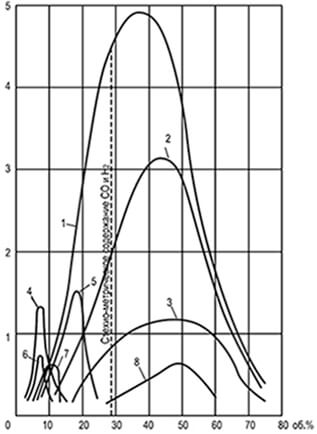
Fig. 8.1. Curves uniform speeds
spreading the flame U n, defined
in the tube with a diameter of 25.4 mm
1-hydrogen; 2-water gas; 3-carbon oxide;
4-ethylene; 5-coke gas; 6-Ethan; 7-methane;
8-generator gas steam-aircraft
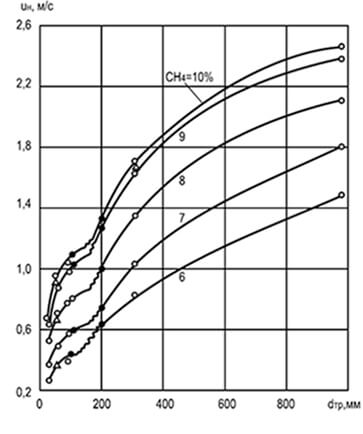
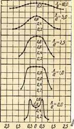
Fig. 8.2. The effect of diameter D Tr and concentration
methane in a mixture with air to change
uniform speed of spreading the flame U n
Experiments have established that the rate of propagation of the flame depends on the diameter of the cylindrical tube, according to which it distributes: the larger the diameter, the higher the speed of the propagation. An increase in the diameter of the tube reduces the effect of the walls on the combustion process and moving the flame front and helps to enhance convection (Fig. 8.2). The analysis of these graphics indicates that with very small sizes of the tubes, the spread of the flame is not at all possible (due to the strong relative heat sink). The dimensions of the tubes, channels and cracks in which the flame does not apply, are called critical.
They are different for different gases:
- cold mixture of methane with air - 3 mm;
- the hydrogen-air mixture is 0.9 mm;
- the warm-up mixture of methane with air is 1.2 mm.
Failure in small section channels are used in practice for creating fireproofers: flamesmaking grids, ceramic porous discs, discs from pressed metal balls, vessels filled with fine-grained materials, etc.); Fire channels in the design of burners operating on gas-air mixtures.
For the comparative characteristics of combustible properties of gases (regardless of the sizes of the tubes), the concept "Normal flame distribution speed" - This is the speed attributed to the cold (still non-flammable) mixture with which the flame moves along the normal to its surface. The flame front is made flat and equal to the diameter of the tube:
u H \u003d W P πR 2 /S(8.22)
where U n is the normal speed of flame propagation, m / s; W P - measured uniform flame propagation rate, m / s; R is the tube radius, m; S - Flame front surface area, m 2.
Table 8.14. Flame propagation velocities in various gas-air mixtures (at t \u003d 20 ° C and p \u003d 103,3cpa), m / s
| Gas | Mixture with maximum normal flame spread speed |
Stoichiometric mixture | ||||
|---|---|---|---|---|---|---|
| Contents in the mixture, about. % | Maximum normal speed distribution |
Contents in the mixture, about. % | Normal speed distribution fame |
|||
| gas | air | gas | air | |||
| Hydrogen | 42,0 | 58,0 | 2,67 | 29,5 | 70,5 | 1,6 |
| Carbon oxide | 43,0 | 57,0 | 0,42 | 29,5 | 70,5 | 0,30 |
| Methane | 10,5 | 89,0 | 0,37 | 9,5 | 90,5 | 0,28 |
| Ethane | 6,3 | 93,7 | 0,40 | 5,7 | 94,3 | 0,32 |
| Propane | 4,3 | 95,7 | 0,38 | 4,04 | 95,96 | 0,31 |
| n-buthin | 3,3 | 96,7 | 0,37 | 3,14 | 96,86 | 0,30 |
| Ethylene | 7,0 | 93,0 | 0,63 | 6,5 | 93,5 | 0,5 |
| Propylene | 4,8 | 95,2 | 0,44 | 4,5 | 95,5 | 0,37 |
| Boutylene | 3,7 | 96,3 | 0,43 | 3,4 | 96,6 | 0,38 |
| Acetylene | 10,0 | 90,0 | 1,35 | 7,75 | 92,25 | 1,0 |
As can be seen from the data table. 8.14, the maximum rate of propagation of the flame corresponds to the mixtures of gas and air with a disadvantage of the oxidant (not stoichiometric). In an excess of flammable, the effectiveness of the collision of the reacting particles and the rate of chemical reactions increases.
Flame propagation speeds for gas oxygen mixtures are an order of magnitude higher than for gas-entertainment. Thus, the maximum normal rate of propagation of the flame of the methane-oxygen mixture is 3.3 m / s, and for a mixture of propane and butane with oxygen - 3.5-3.6 m / s.
The maximum normal flame propagation rate in a mixture of complex gas with air, m / s, is determined by the formula:
u n Max \u003d (R 1 U 1 + R 2 U 2 + ... + R n u n) / (R 1 + R 2 + ... + R n) (8.23)
where R 1, R 2, ... R n is the content of individual components in a complex gas, about. %; U 1, U 2, ... u n - Maximum normal velocities for the propagation of flame components of complex gas in a mixture with air, m / s.
The reduced ratios are suitable for gases with close normal flame propagation rates, for example, for natural and liquefied hydrocarbon gases. For mixtures of gases with sharply different rates of flame propagation (for example, for mixtures of natural and artificial gases, mixtures with a high hydrogen content), they only give approximate values.
If the mixture contains ballast impurities (nitrogen and carbon dioxide), then for approximate calculation of the rate of flame propagation, the formula should be used:
u B \u003d U n MAX (1 - 0.01N 2 - 0,012SO 2) (8.24)
Significantly increases the rate of flame propagation heated gas-air mixture:
and 'n \u003d and n (t' / t) (8.25)
where and 'H - the spread of the flame in the heated mixture with the absolute temperature T', K; and n - the same, in a cold mixture with temperature T, K.
Pre-heating of the mixture changes its density inversely proportional to the absolute temperature, therefore the rate of flame propagation increases in proportion to this temperature. This fact must be taken into account when calculating, especially in cases where fire channels of the burners are located in a heated masonry or when they affect them the radiation of the furnace, hot gases, etc.
The uniformity of the spread of the flame is possible in the following conditions:
- the fire tube has a small length;
- the burning propagates at a constant pressure close to the atmospheric.
If the length of the tube is significant, the uniform distribution of the flame for some mixtures can go into vibration, and then into detonation with a supersonic combustion rate (2000 m / s or more), when the mixture ignition occurs due to the shock wave, heating the mixture to temperatures, exceeding self-ignition temperature. Detonation occurs in the mixtures with high rates of flame spread. The limits of the concentration of detonation are already limits of flammability of gas-air and gas particle mixtures, about. %: Propane - 3.2-37, isobutan - 2.8-31, hydrogen - 15-90. The pressure arising from detonation combustion may exceed the initial ten times and lead to the destruction of pipes and other vessels designed for high pressure.
8.7. Burning in laminar and turbulent fluxes

Fig. 8.3. Front of burning
gas-air mixture B.
laminar Motion Mode
The flame front can be stopped if you create a counter movement of a combustible mixture at a speed equal to normal flame propagation rate. A visual example is the surface of the inner cone of the Bunzen burner. Due to the regulation of the composition of the gas-air mixture arising from the burner during laminar mode of movement, it is possible to achieve a stable and sharply outlined cone of burning (Fig. 8.3). The side surface of the cone (front of the flame), fixed relative to the fire edge of the burner channel, moves towards the flowing gas-air mixture, and the flame in this case extends normal to the ignition surface at each point. On the surface of the cone front of the flame, the equality of speeds is preserved - projections of the flow rate of the gas-air mixture to the normal of the WN to the forming cone and the normal rate of propagation of the flame U n are obeyed by the law of Michelson:
w H \u003d W Pot Cosφ \u003d U H (8.26)
where φ is the angle between the flow direction and the normal to the surface of the cone front of the flame; W Pot - the average flow rate of the gas-air mixture passing through the burner per unit of time, m / s.
The constancy of the normal flame propagation rate is valid only for the main part of the side surface of the cone flame front. In the top of the cone, the speed increases due to the heating of the gas-air mixture closely located areas of the conical surface of the flame front, and at the base of the cone - it is reduced due to the cooling effect of the end of the fire channel of the burner.
For practical calculations, it is usually neglected by this difference and take the speed of the mixture through the front of the flame constant over the entire surface of the cone and equal to U n.
Averaged normal flame propagation rate is equal
u H \u003d V cm / s (8.27)
where V cm is the volume passing through the burner of the gas-air mixture, S is the surface area of \u200b\u200bthe cone front of the flame.
In practice, the tapered front of the flame does not have the right geometric shape, therefore, to accurately determine the flame photograph, the front of the flame is divided into a number of truncated cones. The sum of the side surfaces is the total surface of the cone flame front. The values \u200b\u200bof the normal flame propagation rates defined as the method of the Bunzen burner and other methods are the same and equal to the normal velocities shown in Table. 8.14.
The height of the conical front of the flame depends mainly on the size of the fire channel burner. The decrease in the height of the flame can be achieved by the crushing of large firing channels into several small. For the same gas-air mixtures, the height of the conical fronts of the flame of small channels h can be approximately determined at the height of the front of the single channel n:
h \u003d H / √N (8.28)
where n is the number of small channels.
For burners with high thermal power (burners of industrial boilers, furnaces, etc.), burning, as a rule, occurs in a turbulent stream - a smooth cone front of the flame due to the vortex motion and pulsations is blurred and loses clear conical outlines. At the same time, two characteristic types of burning are observed, corresponding to small-scale turbulence.
With the scale of turbulence not exceeding the thickness of the laminar burning zone, the cone front of the flame retains its shape and remains smooth, although the combustion zone increases. If the scale of turbulence exceeds the thickness of the zone of normal burning, the surface of the cone front of the flame becomes uneven. This leads to an increase in the total surface of the combustion front and burning more fuel mixture per unit of cross-section of the flow.
With large-scale turbulence, significantly higher than the thickness of the zone of laminar burning, the excitement of the surface of the flame front leads to the separation of individual particles of the hot mixture, crusing subsequent ripples. The front of the flame loses its integrity and turns into a system of individual burning foci in the form of equal, dissembly and combustible particles in the stream of a combustible mixture.

Fig. 8.4. Change relative speed
spicy coke gas flame
in the mixture with air depending on the number
Reynolds and Motion Mode Movement
With large-scale turbulence, the surface of the flame front, clamping from the surfaces of all burning particles, increases, leading to a sharp increase in the rate of propagation of the flame (Fig. 8.4). In this case, not only front combustion can occur, propagating at the normal rate V n, but also the volumetric, which occurs due to turbulent ripples of hot burning products in a fresh mixture. Consequently, the total rate of flame propagation under large-scale turbulence is determined by one or another combination of elements of front and volumetric burning.
In the absence of ripples, the turbulent combustion rate becomes equal to normal flame propagation rate. On the contrary, if the pulsation speed significantly exceeds normal, the turbulent combustion rate becomes little dependent on the physico-chemical properties of a combustible mixture. Experiments showed a small dependence of the combustion rate of various homogeneous gas-air mixtures with α\u003e 1 in industrial furnaces from the normal flame propagation rate.
8.8. Sustainability of burning
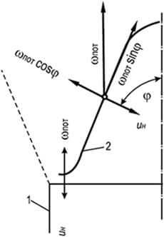
Fig. 8.5. Direct compensation scheme
u H \u003d W sweat with laminar motion
gas-air mixture
1 - wall of the burner;
2 - Flame Front
The main factors affecting the stability of burning are the expiration rate of the gas-air mixture and the spread of the flame. When combustion of gas-air mixtures in a laminar stream, a stable part of the cone front of the flame is its lower part. In this place, the flame front due to the expansion of the gas-air mixture flowing into the atmosphere and the braking the channel wall is deployed to the horizontal and raised over the edge of the channel to the thickness of the flame front (Fig. 8.5).
In this section of the front, a complete compensation of the speed of the gas-air flow rate of the flame propagation U n \u003d W sweat occurs. In the rest of the conical section of the flame front, compensation has a partial character and is carried out only in the direction, normal to the combustion front: U H \u003d W sweat cosφ. Pot SinΦ remains unbalanced and demolides the ignition point from the base of the cone to its vertex. The stability of the cone front of the flame is explained by the ring belt at the base serves as an ignition source, without which the rest of the front would be demolished by the flow of a gas-air mixture.
If the rate of expiration of the mixture exceeds the rate of flame propagation, the width of the ignition belt decreases until it becomes negligible. In this case, the stability of the flame front is broken, and the torch is separated from the burner. If the rate of propagation of the flame in the annular wall area (not on the wall) will exceed the rate of expiration of the gas-air mixture, the flame is drawn inside the burner mixer (skip).
When separating is observed:
- flame breakdown with burner and its extinction;
- separation from the edge of the fire channel when the flame reaches a new enough stable position in the stream over the burner;
- disruption raised flame and its extinction;
- garbage of the raised torch to the edge of the fire channel of the burner;
- creating a weighted flame when the jet ignition is at some distance from the burner.
All these phenomena are not allowed, as they lead to accumulation in the surrounding atmosphere or in the furnace of the unburned gas.
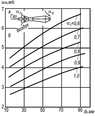
Fig. 8.6. The dependence of the speed of the separation of solitary
flame in an open atmosphere of natural mixtures
gas with air from the size of the fire canal and
the content of primary air.
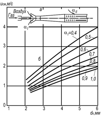
Fig. 8.7. Dependence of the speed of separation
multifacelle flame in an open atmosphere
natural gas mixtures with air from size
fire channel and primary air content.
a - burner scheme; B - Flame Open Curves
In fig. 8.6 Experimental flames from the edges of the firewalls of injection single-packing burners operating on a mixture of cold gas with air are shown. On the border and above these curves, the flame is beaten, and below the curves - sustainable burning.
In practice, multifacelle injection burners with firing channels with a diameter of 2-6 mm are widespread (Fig. 8.7). Establishing the speed of the flames of W OTP for such burners can be made according to the following formula:
w OTR \u003d 3.5 10 -3 D K T 2 (1 + V T) / (1 + α 1 V T) (8.29)
where d k is the diameter of the fire channels, m; α 1 is an excess of primary air coefficient; T - absolute temperature of the gas-air mixture, K.
According to the formula, it can be seen that the burning stability grows with an increase in the diameters of fire channels and temperatures and decreases with an increase in the excess of primary air excess coefficient. The burning stability is also rising due to the mutual influence of the flame.
The separation of the flame from fire channels can occur due to other reasons. With the wrong location of the burner and channels of burning products, they can get into the burner injector and lead to a flame separation (due to the reduction of the flame propagation rate in a gas-air mixture diluted with inert gases). Also, the cause of the separation can be a high velocity of secondary air blowing the flame from the fire channels.
Table 8.15. The speed of a homogeneous mixture of natural
gas with air at which there is a slip
flame, m / s (temperature of the mixture 20 ° С)
| Diameters fires channels |
Primary air excess coefficient | |||||
|---|---|---|---|---|---|---|
| 0,6 | 0,7 | 0,8 | 0,9 | 1,0 | 1,1 | |
| 3,5 | 0,05 | 0,10 | 0,18 | 0,22 | 0,23 | 0,21 |
| 4,0 | 0,08 | 0,12 | 0,22 | 0,25 | 0,26 | 0,20 |
| 5,0 | 0,09 | 0,16 | 0,27 | 0,31 | 0,31 | 2,23 |
| 6,0 | 0,11 | 0,18 | 0,32 | 0,38 | 0,39 | 0,26 |
| 7,0 | 0,13 | 0,22 | 0,38 | 0,44 | 0,45 | 0,30 |
| 8,0 | 0,15 | 0,25 | 0,43 | 0,50 | 0,52 | 0,35 |
| 9,0 | 0,17 | 0,28 | 0,48 | 0,57 | 0,58 | 0,39 |
| 10,0 | 0,20 | 0,30 | 0,54 | 0,64 | 0,65 | 0,43 |
Also inappropriate flames inside the burner mixer, usually accompanied by cotton. Squirt leads either to the population of the flame and the release of a unburned mixture into the room or firebox, or to the burning of the mixture inside the burner. The trend of the flame to the slippery depends on the type of gas, the normal spread rate of the flame, the content of the primary air in the gas-air mixture, the size of the fire channels, the temperatures of the mixture or walls of the channels. The effect on the flame spock is also the coefficient of thermal conductivity of materials from which fire channels are made, their shape, depth and quality of manufacture, the presence of bursts, bugs of the edges, etc.
Led in Table. 8.15 The values \u200b\u200bof the velocities of homogeneous mixtures of natural gases with air, at which there is a slip, can be used for other gases, taking into account the amendments:
w "PR \u003d W PR U" N / U N (8.30)
where W 'PR is the rate of a flame slippery for another gas, m / s; W PR - the velocity rate for natural gas (according to Table 8.15), m / s; U 'H is a normal flame propagation rate for another gas, m / s; U H is the rate of flame propagation in methane, m / s.
The maximum speed of the slippery can be calculated by the approximate formula:
w PR \u003d 0.73 10 -3 D K T 2 (8.31)
The same formula with sufficient approximation can be guided for other gases with the introduction of an amendment to a change in the normal rate of the PACPOPOCTATURE OF FLAME. Based on numerous experiments, you can draw the following conclusion: the limits of stable operation of the burners are limited to the speed of the separation and slippoint of the flame.
Fig. 8.8. The dependence of the velocity of the gas-air mixture at which the flame is separated and the spike, from the excess of primary air coefficient
I - collapse of the flame; II - Flame Squirt; III - Yellow edges of the flame;
1-3 diameters of fire channels burners, mm: 1 - 25, 2 - 25, 3 - 32
In fig. 8.8 The curves are shown that characterize the flow rate of a mixture of natural gas with air under which a margin of flame occurs. The nature of the curves indicates a sharp decrease in flame resistance as the content increases in the primary air mixture. The increase in the stability of the flame occurs when the content of primary air decreases and reaches the maximum when it decreases to zero (diffusion burning). However, such incineration of hydrocarbon gases in many cases is unacceptable, since it leads to the appearance of yellow flames that characterize the appearance of sage particles in it.
Fig. 8.9. Common combustion stabilizers
a - cylindrical tunnel with a sudden expansion of the section;
b - the same, when the stream is swirled;
b is a conical tunnel when the stream is swirling;
g - stabilizer in the form of a conical body;
d - the same, in the form of a round rod;
e - the same, in the form of a steady ring flame
1 - burner fire nozzles; 2 - Tunnel; 3 - side opening;
4 - Ring Channel; 5 - ring flame;
6 - Flame of the main stream of gas-air mixture
In practice, to expand the range of burning stability of any combustible gas-air mixtures, the flow rate is accepted several times greater than the speed of the separation. The prevention of the separation of the flame is achieved by the use of combustion stabilizers (Fig. 8.9).
To stabilize the flame of injection and other burners issuing axisymmetric gas-air jets, refractory cylindrical tunnels are used with a sudden expansion of their cross section. The effect of such a tunnel is based on the peripheral circulation of the part of the hot combustion products arising from the rolled jet.
To stabilize the flame of burners, outstanding a swirling gas-air mixture, are used both cylindrical and conical tunnels with an angle of disclosure 30-60 °. With a swirling stream on the periphery of the tunnel, there is a greater pressure than in its central part. This leads to a rapid recycling of the part of the hot combustion products and the ignition of the cold gas-air mixture flowing into the tunnel of the cold gas-air mixture.
When the setting of the tunnels is not possible, the bodies of a poorly streamlined form are used to stabilize the flame, located in the flow of the gas-air mixture at the outlet of it from the fire channel of the burner. The ignition of the mixture occurs on the periphery of the stabilizer, which arises a partial recycling of hot gases, igniting the combustible mixture from the inside. The stabilizing effect of such devices is lower than the tunnels.
In the injection unit, stabilizers of combustion in the form of a special fire nozzle are widely used in the injection of one or multifacelle burners. The stabilizing effect of this device is based on preventing the dilution of the main stream at the root of the torch with excess air, which narrowes the limits of its stability, as well as heating and igniting the ring flame of the main flow throughout its periphery. The stability of the ring flame during the separation is achieved due to this ratio of the cross sections of the fire ring and side holes, in which the speed of the gas-air mixture in the annular cavity does not exceed the normal spread rate of the flame. To prevent the flame slip into the burner mixer, the size of the side holes forming the ring flame are accepted by smaller critical.
8.9. Schemes of fireproofers
Air or oxygen, hitting the gas pipeline, can form an explosive mixture, so it is necessary to prevent pipelines from the penetration of air or oxygen into it. All hazardous industries should create conditions that exclude the possibility of igniting impulses. Sources of ignition, resulting in gas-air mixtures to the explosion, are:
- open flame;
- electrical discharges of existing electrical equipment;
- short circuit in electrical wires;
- springs in electrical devices;
- bind of open fuses;
- static electricity discharges.
Explosion safety is provided by various fireprocerers. installed in pipelines, on tanks, on purge gas pipelines, candles and other systems, where there is a danger of explosion.
The population of the flame in the channel filled with a combustible mixture occurs only with the minimum diameter of the channel, depending on the chemical composition and pressure of the mixture, and is explained by the heat loss from the reaction zone to the channel walls. With a decrease in the diameter of the channel, its surface increases by a unit of mass of the reacting mixture, i.e. Heat loss is increasing. When they reach a critical value, the rate of combustion reaction decreases so much that the further spread of the flame becomes impossible.
The flavening ability of the fireprocessor depends mainly on the diameter of the quenching channels and much less - from their length, and the possibility of the penetration of the flame through the resulting channels depends mainly on the properties and composition of the combustible mixture and pressure. The normal flame propagation rate is the primary value determining the size of the amounts of quenching channels and the choice of a fireprocessor type: how it is more, the smaller the channel is required to clean the flame. Also, the sizes of quenching channels depend on the initial pressure of the combustible mixture. To assess the flame-making ability of fireprocerers, the so-called. Pakele's criterion:
Re \u003d W cm dc p P / (RT 0 λ 0) (8.32)
In the limit of the flame harvesting formula, the Peklet criterion takes the form:
Rec \u003d W cm D cr c P p cr / (RT 0 λ 0) (8.33)
where W cm is the normal flame propagation rate; d - the diameter of the dividing channel; D Kp - the critical diameter of the divorce channel; C p - specific heat heat capacity at 0 ° C and constant pressure; p - gas pressure; R CR - critical gas pressure; R is a universal gas constant; T 0 is the absolute temperature of the gas; λ 0 - thermal conductivity of the initial mixture.
Thus, for calculating the flameless ability of fireprocers, the following source data is necessary:
- normal speed of propagation of flames of combustible gas mixtures;
- the actual size of the maximum quenching channels of this fireprocessor.
If the value obtained is greater than Rec \u003d 65, the fireprocessor will not detain the spread of the flame of this combustible mixture, and vice versa, if re< 65, огнепреградитель задержит распространение пламени. Запас надежности огнепреградителя, который находят из отношения Ре кр к вычисленному значению Ре, должен составлять не менее 2:
P \u003d RE CR / D \u003d 65 / RE\u003e 2.0 (8.34)
Using the fact of the constancy of the rear in the limit of the flame damage, it is possible to calculate the estimated critical diameter of the channels for any combustible mixture, if the flame propagation rate is known, as well as the heat capacity and thermal conductivity of the gas system. The following critical diameters of the quenching canal are recommended, mm:
- when burning a gas-air mixture - 2.9 for methane and 2.2 for propane and ethane;
- when burning oxygen mixtures in pipes (at an absolute pressure of 0.1 MPa in conditions of free expansion of combustion products) - 1.66 for methane and 0.39 for propane and ethane.
Fig. 8.10. Types of fireprocerers:
a - nozzle; b - cassette; in - lamellar; g - mesh; d - metal ceramics
Constructively fireprocerers are divided into four types (Fig. 8.10):
- with a nozzle from granular materials;
- with straight channels;
- from metal ceramics or metallic fiber;
- mesh.
By the installation method - on three types: on pipes for emissions of gases into the atmosphere or to the torch; on communications; Before gas melting devices.
In the housing of the mounted fireprocessor between the lattices there is nozzle with filler (glass or porcelain balls, gravel, corundum and other granules from durable material). The cassette fireprocessor is a housing in which a firework-grinding cassette from corrugated and flat metal tapes, tightly retained into a roll. In the housing of the plate fireprocessor, a package of plane-parallel metal plates with a strictly defined distance between them. The mesh fireprocerer in the housing is placed a package of tightly compressed metal grids. The metal-ceramic fireprocessor is a housing inside which a porous metal-ceramic plate is installed as a flat disk or tube.
Most often applied mesh fireworks (they began to be installed at the beginning of the XIX century in mining lamps (lamps of Devi) to prevent mine explosions). These fireworks are recommended to protect the installations in which gas fuel is burned. The fireworks element consists of several layers of brass mesh with a cell size of 0.25 mm, sandwiched between two perforated plates. The grids package is reinforced in a removable clip.
The fireprocessor housing is made of cast-iron or aluminum alloy and consists of two identical parts connected by a bolt with a removable clip located between them. In addition to those considered dry flamers, liquid safety shutters, preventing gas pipelines from the entry of an explosive wave and flame in the gas-flowing of metals, as well as pipelines and apparatus filled with gas, from penetrating oxygen and air to them.
Liquid gate should:
- prevent the spread of an explosive wave during reverse strikes and when gas ignition;
- protect the gas pipeline from the oxygen and air enter it;
- provide minimal hydraulic resistance to the passage of gas flow. In addition, the liquid from the shutter should not be carried out in the form of drops in noticeable quantities.
8.10. Principles of burning
The basis of gas burning processes - principles, conventionally referred to as kinetic and diffusion. At the same time, a homogeneous mixture with some excess air is created prior to the beginning of the combustion. The combustion of such a mixture occurs in a short transparent torch without education in the flame of soot particles. For burning gas along the kinetic principle, special mixers or injection burners are used, preparing a homogeneous gas-air mixture with an excess air coefficient α 1 \u003d 1.02: 1.05.
With a smaller content of the primary air on the kinetic principle, only the initial stage of burning is proceeded, prior to the use of oxygen in the mixture with gas. The remaining gases and incomplete combustion products are burned due to the external diffusion of oxygen (secondary air), i.e. For d and f f u s and o n o m at the principle. At α 1.< 1 у факела есть два видимых фронта горения: внутренний, возникающий за счет первичного воздуха, и наружный, образующийся за счет диффузии кислорода из окружающей среды. Общая высота пламени при таком горении возрастает, а температура - несколько снижается. Устойчивость пламени и его прозрачность зависят от содержания первичного воздуха в смеси: чем оно выше, тем ниже устойчивость пламени, больше его прозрачность, и наоборот.
Gas burning principle with α 1< 1,0 является п р о м е ж у т о ч н ы м (между кинетическим и диффузионным). С учетом этого принципа конструируются все газовые аппараты с инжекционными горелками. В таких горелках содержание первичного воздуха в смеси принимается в зависимости от вида газа таким, чтобы:
- in the flame there were no sage particles;
- the combustion stability was ensured when changing thermal power in any limits needed in practice.
With a diffusion principle (α 1 \u003d 0), combustion and mixing processes are developing in parallel. Since mixing processes proceed significantly slower combustion processes, the speed and completeness of the combustion are determined by the speed and completeness of the gas and air mixing. The mixing of gas with air can occur by diffusion (or slow molecular or turbulent, including molecular as the final stage). Accordingly, the combustion rate and the diffusion flame structure differ.
Features of such burning:
- flame resistance when changing thermal power from zero to the maximum possible under the conditions of separation;
- constancy of temperatures over the entire height of the flame;
- the ability to distribute it for large arbitrary surfaces;
- compactness of burners and simplicity of their manufacture;
- a significant height of the flame and the inevitability of pyrolytic processes leading to the formation of a bright sage flame.
Fig. 8.11. The structure of loose flames:
a - laminar flame; b - turbulent flame
Diffusion combustion can be translated into a kinetic or intermediate if the mixing will be ahead of the combustion processes. In practice, this can be achieved forced air supply leading to the formation of a quasi-homogeneous gas-air mixture with α 1\u003e 1.0, combining in a transparent torch.
To illustrate the combustion principles in fig. 8.11. Schemes of free torches are shown: laminar and turbulent. Laminar torch arises due to mutual molecular diffusion of gas and air. Inside the conical kernel 1 is pure gas flowing from the tube during laminar flow mode. In zone 2 - a mixture of gas and combustion products, in zone 3 - a mixture of combustion and air products. The boundary 4 is a smooth conical front of the flame, to which the air molecules diffuse outside, and from the inside - the gas molecule. Combustion products partially diffuse to meet with gas, intensively heating it in the suspension zone. This leads to the pyrolysis of hydrocarbons and the formation of sage particles that give flames bright luminosity.
Intensify combustion can be due to the turbulization of mixing flows. A turbulent torch has no clear conical burning front, it is "blurred" and fragmented with ripples on separate particles.
The structure of the flame consists of a core of pure gas 1, the zone of relatively slow burning 2, the blurred zone of the most intense combustion 3 with a high content of combustion products and a combustion zone 4 with a predominance of air in it. There are no clearly pronounced boundaries between zones, they are continuously shifted depending on the degree of flow turbulization. The peculiarities of a turbulent torch are:
- the flow of burning process is almost all over the volume;
- increasing burning intensity;
- big flame transparency;
- ligger its stability towards the separation.
Turbulent gas burning is widely used in the furnaces of various boilers and stoves. To intensify the combustion process, both natural (by increasing speeds) and artificial, turbulization of flows, such as the twisting of the air flow and supplying it at various angles of thin gas jets in various angles.
8.11. Conditions for the formation of incomplete combustion products and a decrease in the concentration of harmful substances
When combustion of combustible gases, combustion products may contain components of both complete (carbon dioxide and water vapor) and incomplete combustion (carbon monoxide, hydrogen, unsaturated, saturated, aromatic hydrocarbons and sage particles). In addition, nitrogen oxides are always detected in combustion products. The presence of incomplete combustion products in significant concentrations is unacceptable, as it leads to the contamination of the atmosphere toxic substances and to a decrease in the efficiency of installations operating on gas fuel.
The main reasons for their large content:
- burning gases with insufficient air;
- bad mixture of combustible gases and air before and in the process of burning;
- excessive flame cooling until the combustion reactions are completed.
For methane combustion reaction (depending on the oxygen concentration in the reactive mixture) can be described by the following equations:
CH 4 + 2O 2 \u003d CO 2 + 2N 2 O + 800.9 MJ / mol
with a stoichiometric ratio or in an excess of the oxidant;
CH 4 + O 2 \u003d CO + H 2 + H 2 O + Q and CH 4 + 0.5O 2 \u003d CO + 2H 2 O + Q
with a disadvantage of the oxidant.

Fig. 8.12. Intermediate combustion products
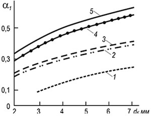
Fig. 8.13. Primary air content
in which education is prevented
yellow languages \u200b\u200bin flame
Gas: 1 - coke;
2 - Natural Gas deposits;
3 - oil deposits;
4 - propane; 5 - Bhutan
In fig. 8.12 shows an approximate average composition of some intermediate compounds - hydrogen, carbon oxide, ethylene, acetylene and a relatively small number of saturated and simple aromatic compounds - and carbon dioxide arising in flame with diffusion burning of natural gas (97%). Gas burning was produced in a laminar torch, gas flowed from a pipe with a diameter of 12 mm. Total flame height 130-140 mm.
The maximum concentration of hydrogen and acetylene is achieved at about one altitude of the flame, they disappear almost simultaneously at the top of the flame glowing zone. Of all the intermediate compounds formed in the flame (excluding sage particles) carbon oxide disappears the last. This gives reason to judge its index on the completeness of the gas combustion. In combustion products, nitrogen oxides are always present, the maximum concentration of which occurs in the zones of intensive burnout of carbon monoxide and hydrogen.
The burning of hydrocarbon gases with a disadvantage of the oxidizer leads to the formation of particles of soot that give the flame yellow color. The soap burning process proceeds stadium and relatively slow. Sometimes the burnout of the resulting particles of soot is delayed and can be ceased fully at the entrance to the low-temperature region of the torch or when the flame is washed with the flame of heat exchange surfaces. Thus, the presence of a luminous flame always demonstrates the flow of pyrolytic processes and the possibility of chemical incompleteness of combustion, especially in small-sized shielded fireboxes of boilers.
Preventing the formation of sage particles is achieved by preliminary mixing of hydrocarbon gases with a sufficient amount of oxidizing agent. The primary air content in the mixture in which the transparent flame occurs, it depends not only on the type of hydrocarbons, but also on the conditions of mixing with the secondary air (the diameter of the fire channels of the burner) (Fig. 8.13). On the border and above the curves of the flame transparently, and below the curves has yellow tongues. The curves show that the primary air in the mixture increases with increasing number of carbon atoms in the molecule, and the diameter of the burner firing channels. The excess of primary air coefficient α 1 in the mixture, in which the yellow flames disappear, depending on the specified factors, can be determined for small fire channels of the burner:
α 1 \u003d 0.12 (M + N / 4) 0.5 (D K / D 0) 0.25 (8.35)
where m and n are the number of carbon and hydrogen atoms in the molecule or the average number for the complex gas; d k - the diameter of the fire channels of the burner, mm; D 0 - the reference diameter of the burner channel (1 mm).
Ensuring completeness of combustion in practical conditions - the task is quite complicated, depending not only on the principle of burning gas, but also on the conditions of the development of the flame in the winding volume. The highest demands on complete combustion are presented to household apparatus and other settings, discarding combustion products into the atmosphere. The combustion of gas in such installations is the most difficult, as it is associated with the washing with the flame of cold heat exchange surfaces. For burning gas in household plates, injection multifacelle burners are used, forming a homogeneous mixture with a coefficient of excess primary air α 1< 1. Недостающий для сгорания газа воздух поступает за счет диффузии из окружающей атмосферы.
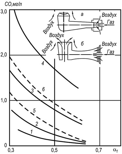
Fig. 8.14. Concentration of carbon oxide
in combustion products in a gas stove
a - burner with peripheral supply of secondary air;
b - with central and peripheral feeding of secondary air
1 - Natural gas, burner with peripheral
secondary air, distance to bottom of the dishes 25 mm;
2-4 - natural gas, burner with perifier and
central submarine of secondary air, distance
to the bottom of the dishes, mm: 2 - 25, 3 - 18, 4 - 10;
5 - liquefied gas, burner with central and peripheral
submarine of secondary air, distance to bottom of the dishes 25 mm;
6 - liquefied gas, burner with peripheral
In fig. 8.14 2 shows circuit-ring burners for domestic gas cookers and the average carbon monoxide concentration CO in the combustion products of natural methane (95 vol.%) And propane (93 vol.%) When using the burner with a nominal thermal capacity. The difference in the burner is that the secondary air is supplied to one of them only from the periphery, and to the other, both from the periphery and from the central channel.
The completeness of the gas combustion depends on the excess of the primary air in the mixture, the distance from the fire channels of the burner to the bottom of the dishes, the form of a fuel gas, the method of supplying secondary air. At the same time, an increase in the content of primary air in the mixture, as well as an increase in the distance from the burner to the bottom of the dishes lead to a decrease in the concentration of carbon oxide in combustion products. The minimum concentration of carbon oxide corresponds to the coefficient of excess primary air α 1 \u003d 0.6 and above and the distance from the burner to the bottom of the dishes of 25 mm, and the maximum - α 1 \u003d 0.3 and below and the distance from the burner to the bottom of the dishes 10 mm. Moreover, increasing the thermal power of burners 15-20% by increasing the gas pressure increases the concentration of carbon monoxide in the combustion produk max 1.2-1.3 times, and by the heat of the combustion gas - 1.5-2 times.
On the appearance in the process of combustion of aromatic compounds - benzene, polycyclic benzpyrin, non-law, etc. - special attention should be paid, as some of them are carcinogenic. The process of their formation is very complex and proceeds stadium. At the first stage, acetylene and its derivatives appear. In the flame zone, these substances undergo the processes of lengthening the chain with the restructuring of triple carbon ties to double. As a result of cyclization and dehydration, lead to the emergence of various aromatic compounds, including polycyclic.
Table 8.16. The average concentration in the combustion products of carbon monoxide and benz (a) of the pyrene, depending on the type of gas, the type of burner and the excess of primary air (thermal burner load - 1600 kcal / h, the distance from the burner to the bottom of the dishes - 24-26 mm)
| Type of burner | Average concentration | |
|---|---|---|
| carbon oxide, mg / l (in terms of α \u003d 1.0) |
benz (a) pyrene, μg / 100 m 3 |
|
| Natural gas | ||
at α i \u003d 0.60 ÷ 0,70 |
0,10 | Not found |
at α i \u003d 0.30 ÷ 0.35 |
1,20 | Traces |
at α i \u003d 0.60 ÷ 0,70 |
0,50 | Not found |
at α i \u003d 0.30 ÷ 0.35 |
0,12 | Not found |
| Liquefied hydrocarbon gas | ||
| The burner with the peripheral submarine of secondary air: | ||
at α i \u003d 0.60 ÷ 0,70 |
0,30 | 0,03 |
at α i \u003d 0.30 ÷ 0.35 |
1,20 | 1,10 |
| Burner with central and peripheral submarines of secondary air: | ||
at α i \u003d 0.60 ÷ 0,70 |
0,07 | 0,02 |
at α i \u003d 0.30 ÷ 0.35 |
1,00 | 0,045 |
Data Table. 8.16 show that the combustion of natural gas with the primary air excess factor α 1 \u003d 0.6 and up burners on both types of carbon monoxide concentration of the combustion gas meets the requirements of GOST 5542-87.
Table 8.17. The distance between the edges of the firing channels, single injection burners depending on their size and primary air excess factor
| Fire channel diameters, mm | Distances between the edges of the channels, mm at different values \u200b\u200bof the overtime air coefficient α 1 | ||||
|---|---|---|---|---|---|
| 0,2 | 0,3 | 0,4 | 0,5 | 0,6 | |
| 2,0 | 11 | 8 | 6 | 5 | 4 |
| 3,0 | 15 | 12 | 9 | 7 | 5 |
| 4,0 | 16 | 14 | 11 | 9 | 7 |
| 5,0 | 18 | 15 | 14 | 12 | 10 |
| 6,0 | 20 | 18 | 16 | 14 | 12 |
Studies have shown that the distances between the edges of the firewesters, providing the rapid spread of the flame, preventing their merge depend on their size and the content of primary air in the mixture, decreasing with its increase. The optimal distances between the edges of the channels, providing sufficient completeness of the combustion of the gas and the rapid spread of the flame, are given in Table. 8.17. When the fire channels are arranged in two rows in a checker order, the distance between the edges can be accepted along the same table. The distances between the rows should be 2-3 times the distances between the channels.
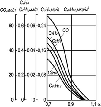
Fig. 8.15. Carbon oxide concentration, acetylene,
ethane, ethylene and benz (a) pyrene in combustion products
middle Pressure Gas In Injection Burner
Generalization numerous experimental data yielded curves averaged concentration in the combustion products of the various components, both qualitatively and quantitatively characterize the combustion process (Fig. 8.15). The complete combustion of the homogeneous gas-air mixture is achieved only with the excess of primary air coefficient α \u003d 1.05 and higher. With a decrease in the air content in the mixture, especially when α< 1,0, возрастает концентрация оксида углерода СО, ацетилена С 2 Н 2 , этилена С 2 Н 4 , пропилена С 3 Н 6 и пропана С 3 Н 8 , а также бенз(а)-пирена С 20 Н 9 . Также возрастает концентрация и других компонентов - водорода, бензола и др.
Also considered products of incomplete combustion, the combustion of the gas is always a certain amount of nitrogen oxide formation which occurs in areas of high temperatures after the completion of the basic reactions of combustion and during the combustion process. The maximum concentration of NO x occurs at the final stages corresponding to the burnout of the gas and the intensive combustion of intermediate products in the form of hydrogen and carbon oxide.
Primary compound when combustion of gas-air mixtures - nitrogen oxide. The beginning of the chain reaction is associated with atomic oxygen arising in high temperatures due to the dissociation of molecular oxygen:
O 2 -\u003e 2O - 490 kJ / mol (8.36)
O + N 2 -\u003e NO + N - 300 kJ / mol (8.37)
N + O 2 -\u003e 2NO + 145 KJ / Mol (8.38)
Balance reaction
N 2 + O 2 -\u003e 2NO - 177 KJ / Mol (8.39)
The formation of atomic oxygen occurs during partial dissociation of combustion products: with a decrease in the temperature and oxygen, a part of the formed nitrogen oxide (1-3% by volume) is oxidized until nitrogen dioxide NO 2. The most intense reaction proceeds after the release of nitrogen oxide into the atmosphere. Basic influencing factors:
- temperature in reaction zones;
- the excess air coefficient and the contact time of the reacting components.
The flame temperature depends on the chemical composition of the gas, the air content in the gas-air mixture, the degree of its homogeneity and the heat sink from the reaction zone. The maximum possible concentration of nitrogen oxide, about. % can be calculated by the formula
NO P \u003d 4,6E -2150 / (RT) / √O 2 N 2 (8.40)
where NO P is the equilibrium concentration of nitrogen oxide, about. %; R is a universal gas constant; T - absolute temperature, to; O 2 and N 2 - concentration, about. %, respectively oxygen and nitrogen.
The high concentration of nitrogen oxide, commensurable with an equilibrium, occurs when burning gas in the furnaces of powerful steam generators and in high-temperature Marten, coke and similar furnaces. In small and medium power boilers, in small heating and thermal furnaces with a significant heat sink and low time of the residence components in high-temperature zones, the yield of nitrogen oxide is an order of magnitude less. In addition, the shorter the time of the residence of the reacting components in the high temperature zone, the less nitrogen oxide in combustion products.
It is also effective combustion gas in radiant burners in the fluidized bed in these cases occurs mikrofakelnoe homogeneous combustion gas mixture with the air excess factor α \u003d 1,05 with very intensive heat removal from the reaction zone. The concentration of nitrogen oxides during gas burning in the radiating burners is about 40, and in a fluidized bed - 80-100 mg / m 3. Reducing the size of the fire channels of emitting torches and refractory grains in the fluidized bed helps to reduce the yield of nitrogen oxides.
The accumulated data made it possible to make a number of changes in the design of boiler-heating equipment, providing not only the high efficiency and low concentration of incomplete combustion products, but also a reduced reset to the atmosphere of nitrogen oxides. These changes include:
- reducing the length of high-temperature tunnels and move the burning of them in the furnace;
- application instead of ceramic tunnels of burning stabilizers in the form of bodies of a poorly added shape or ring flame;
- organization of a flat flame torch with an increased heat transfer surface;
- flame dispersal due to increasing the number of burners or using block burners;
- stepped air supply to the reaction zone;
- uniform distribution of heat fluxes in the furnace, shielding of the furnace and their separation on the screen compartments;
- the use of the diffusion principle of gas burning (diffusion combustion is permissible only in cases where the free development of the flame can be provided without washing the heat exchange surfaces).
The most effective reduction in nitrogen oxide yield is achieved while using several methods.
Gas burning is a combination of the following processes:
· Mixing a combustible gas with air,
· Heated mixture,
· Thermal decomposition of combustible components,
· Ignition and fuel components chemical compound with oxygen, followed by the formation of flame and intense heat.
Methane burning occurs by reaction:
CH 4 + 2O 2 \u003d CO 2 + 2N 2
The conditions necessary for the combustion of gas:
· Ensuring the necessary combustion of combustible gas and air,
· Heating to ignition temperature.
If in the gas-air gas mixture is less than the lower limit of ignition, then it will not burn.
If there is more gas in the gas-air mixture than the upper limit of ignition, it will not be completely burned.
The composition of the products of full combustion of gas:
· CO 2 - carbon dioxide
· H 2 O - Water Couples
* N 2 - nitrogen (it does not react with oxygen during burning)
The composition of the products of incomplete combustion of gas:
· CO - Durger gas
· C - soot.
For combustion of 1 m 3 of natural gas, 9.5m 3 air is required. Almost the air flow is always more.
Attitude valid flowair to theoretically required flowit is called an excess air coefficient: α \u003d L / L t.,
Where: L - valid flow;
L T is theoretically necessary consumption.
The excess air coefficient is always more than one. For natural gas, it is 1.05 - 1.2.
2. Purpose, Device and main characteristics of flowing water heaters.
Flowing gas water heaters. Designed to heat the water to a certain temperature during a water treatment .. flow water heaters are divided by thermal power load: 33600, 75600, 105000 kJ, according to the degree of automation - to the highest and first classes. Kpd. Water heaters 80%, oxide content of no more than 0.05%, temperature of combustion products for a burden of not less than 180 0 C. The principle is based on heat heating during the water-based period.
The main nodes of flowing water heaters are: a gas-melting device, heat exchanger, automation system and a gas feed. Low pressure gas is supplied to the injection burner. Combustion products pass through the heat exchanger and are discharged into the chimney. The heat of the combustion is transmitted through the water flowing through the heat exchanger. For cooling the fire chamber serves as a coil, through which the water circulates through the canorior. Gas flowing water heaters are equipped with gas feeding devices and burden, which, in the case of short-term violation, traction prevent the flame of the gas melting device. To join the chimney there is a smoking nozzle.
Gas flower water heater -VPG.On the front wall of the casing are: a gas crane control knob, an electromagnetic valve switching button and an observation window for monitoring the flames of the fastener and the main burner. At the top of the device there is a chimney device, lower pipes to attach the apparatus to the gas and water system. The gas enters the solenoid valve, the gas blocking valve vodogazogorelochnogo unit performs sequential switch the pilot burner and the gas supply to the main burner.
The blocking of gas flow to the main burner, with the obligatory operation of the fist, is carried out by an electromagnetic valve operating from the thermocouple. Blocking gas supply to the main burner depending on the presence of water treatment, is carried out by a valve having a drive through a rod from the water block membrane.
Natural gas is the most common fuel today. Natural gas is called natural, because it is mined from the very beginning of the Earth.
The gas combustion process is a chemical reaction at which natural gas interacts with oxygen, which is contained in the air.
In the gaseous fuel there is a combustible part and non-combustible.
The main combustible component of natural gas is methane - CH4. Its content in natural gas reaches 98%. Methane does not smell, does not taste and is non-toxic. The limit of its flammability is from 5 to 15%. It is these qualities that made it possible to use natural gas, as one of the main types of fuel. The concentration of methane is life threatening more than 10%, so may suffice, due to the lack of oxygen.
To detect gas leakage, gas is subjected to odorization, in other words, a hazardous substance is added (ethyl mercaptan). At the same time, the gas can be detected at a concentration of 1%.
In addition to methane in natural gas, combustible gases may be present - propane, butane and ethane.
To ensure high-quality combustion of gas, it is necessary in sufficient amounts to bring air into the combustion zone and achieve good gas mixing with air. The optimal is considered to be the ratio of 1: 10. That is, one part of the gas accounts for ten parts of the air. In addition, it is necessary to create the desired temperature regime. In order for gas to ignore it, it is necessary to heat it up to the temperature of its ignition and in the future the temperature should not fall below the ignition temperature.
It is necessary to organize the removal of combustion products into the atmosphere.
Full burning is achieved if there are no combustible substances in the combustion products of the exit to the atmosphere. At the same time, carbon and hydrogen are combined together and form carbon dioxide and water pair.
Visually with full combustion flames light blue or bluish purple.
Full combustion of gas.
methane + oxygen \u003d carbon dioxide + water
CH 4 + 2O 2 \u003d CO 2 + 2N 2
In addition to these gases, nitrogen and remaining oxygen comes to a combustible gas. N 2 + O 2
If the combustion of gas is not completely, the fuel substances are ejected into the atmosphere - carbon monoxide, hydrogen, soot.
Incomplete gas combustion occurs due to insufficient air. At the same time, the Scoot languages \u200b\u200bappear visually in the flame.
The risk of incomplete combustion of gas is that carbon monoxide can cause poisoning boiler room. The content of CO in air 0.01-0.02% may cause light poisoning. Higher concentration can lead to severe poisoning and death.
The resulting soot settles on the walls of boilers worsening the heat transmission to the heat carrier reduces the efficiency of the boiler room. Soot carries out warmly worse than methane 200 times.
Theoretically, the combustion of 1m3 gas is needed 9m3 air. In real air conditions, it takes more.
That is, an excessive amount of air is necessary. This magnitude denoted alpha shows how many times the air is spent more than theoretically, theoretically.
The alpha coefficient depends on the type of the specific burner and is usually prescribed in the duct passport or in line with the recommendations of the organization produced commissioning.
With increasing amount of excess air above the recommended, heat losses are growing. With a significant increase in the amount of air, the flame may occur by creating an emergency. If the amount of air is less than recommended, the burning will be incomplete, thereby creating a threat to poisoning the boiler room.
For more accurate control of the quality of the combustion of fuel, there are gas analyzers, which measure the content of certain substances in the composition of the outgoing gases.
Gas analyzers can be included with boilers. In case there are no, the corresponding measurements conducts a commissioning organization with portable gas analyzers. A modest card is compiled in which the required control parameters are prescribed. By adhering to them, it is possible to ensure normal full combustion of fuel.
The main parameters for regulating fuel combustion are:
- the ratio of gas and air served on the burner.
- camerage of an excess air.
- diffix in the furnace.
- The usefulness of the boiler.
At the same time, under the coefficient of the useful effect of the boiler, the ratio of useful heat to the value of all the expended heat is implied.
The composition of the air
| Gas name | Chemical element | Contents in air |
| Nitrogen | N2. | 78 % |
| Oxygen | O2. | 21 % |
| Argon | AR | 1 % |
| Carbon dioxide | CO2. | 0.03 % |
| Helium | He. | less than 0.001% |
| Hydrogen | H2. | less than 0.001% |
| Neon | Ne | less than 0.001% |
| Methane | CH4 | less than 0.001% |
| Krypton | Kr. | less than 0.001% |
| Xenon | Xe. | less than 0.001% |
The combustion of gaseous fuel is a combination of the following physical and chemical processes: mixing the combustible gas with air, heated mixture, thermal decomposition of combustible components, ignition and chemical compound combustible elements with air oxygen.
Sustainable combustion of the gas-air mixture is possible with a continuous supply to the combustion front of the necessary quantities of combustible gas and air, their thorough stirring and heating to the ignition temperature or self-ignition (Table 5).
The ignition of the gas-air mixture can be carried out:
- heating of the entire volume of the gas-air mixture to the temperature of self-ignition. This method is used in internal combustion engines, where the gas-air mixture is heated by rapid compression to a certain pressure;
- use of foreign ignition sources (stobers, etc.). In this case, the entire gas-air mixture is heated to the ignition temperature, and its part. This method is used when burning gases in gas burners;
- the existing torch is continuously in the process of burning.
To begin the reaction of combustion of gaseous fuel, a certain amount of energy required for the breaking of molecular bonds and creating new ones should be expected.
The chemical combustion formula of gas fuel, indicating the entire reaction mechanism associated with the occurrence and disappearance of a large number of free atoms, radicals and other active particles, is complex. Therefore, it is used to simplify equations expressing the initial and final state of gas combustion reactions.
If hydrocarbon gases are referred to with M N N, then the equation of the chemical reaction of the combustion of these gases in oxygen will take the form
C M H n + (M + N / 4) O 2 \u003d MCO 2 + (N / 2) H 2 O,
where M is the number of carbon atoms in hydrocarbon gas; n is the number of hydrogen atoms in gas; (M + N / 4) - the amount of oxygen required for the total combustion of the gas.
In accordance with the formula, the equations of combustion of gases are derived:
- methane CH 4 + 2O 2 \u003d CO 2 + 2N 2 O
- ethane C 2 H 6 + 3,5O 2 \u003d 2СO 2 + zn 2 o
- butane C 4 H 10 + 6,5O 2 \u003d 4CO 2 + 5N 2 0
- propane C 3 H 8 + 5O 3 \u003d ЗСO 2 + 4N 2 O.
In practical conditions, the gas burning oxygen is not taken in pure form, but is part of the air. Since air consists in volume by 79% of nitrogen and 21% of oxygen, then 100: 21 \u003d 4.76 air volumes or 79: 21 \u003d 3.76 volume of nitrogen is required for each oxygen volume. Then the reaction of burning methane in the air can be written as follows:
CH 4 + 2O 2 + 2 * 3.76N 2 \u003d CO 2 + 2H 2 O + 7.52N 2.
It can be seen from the equation that for burning 1 m 3 of methane requires 1 m 3 of oxygen and 7.52 m 3 nitrogen or 2 + 7.52 \u003d 9.52 m 3 air.
As a result of combustion of 1 m 3 of methane, 1 m 3 carbon dioxide, 2 m 3 of water vapor and 7.52 m 3 nitrogen is obtained. The table below shows this data for the most common combustible gases.
For the combustion process of the gas-air mixture, it is necessary that the amount of gas and air in the gas-air mixture is within certain limits. These limits are called flammability limits or explosability limits. There are lower and upper limits of flammability. The minimum gas content in the gas-air mixture, expressed in volume percent, in which ignition occurs is called the lower limit of flameability. The maximum gas content in the gas-air mixture, above which the mixture is not flammable without the supply of additional heat, is called the upper flameability limit.
The amount of oxygen and air when burning some gases
|
For burning 1 m 3 Gas required, m 3 |
When burning 1 m 3 of gas stands out, m 3 |
Heat combustion he, kj / m 3 |
|||||
|
oxygen |
dioxide carbon |
||||||
|
Carbon oxide |
|||||||
If gas contains gas less than the lower limit of flammability, it will not burn. If there is not enough air in the gas-air mixture, then the burning proceeds not completely.
Inert impurities in gases have a large influence on the magnitude of the explosive limits. The increase in the contents of the ballast gas (N 2 and CO 2) narrows the limits of flammability, and with an increase in the content of ballast above certain limits, the gas-air mixture is not flammable at any ratios of gas and air (table below).
The number of inert gas volumes by 1 fuel gas volume at which the gas-high mixture ceases to be explosive
The smallest amount of air required for the total burning of the gas is called the theoretical consumption of air and is denoted by LT, that is, if the lowest heat combustion of gas fuel 33520 kJ / m 3 , then theoretically necessary amount of air for burning 1 m 3 Gas.
L T.\u003d (33 520/4190) / 1.1 \u003d 8.8 m 3.
However, the valid air flow always exceeds theoretical. This is explained by the fact that it is very difficult to achieve complete combustion of gas in theoretical costs of air. Therefore, any gas unit for burning gas works with some excess air.
So, practical air flow
L n \u003d αl t,
where L N. - practical air flow; α - an excess air coefficient; L T. - Theoretical air flow.
The excess air coefficient is always more than one. For natural gas he is α \u003d 1.05 - 1.2. Coefficient α Indicates how many times the actual air flow exceeds the theoretical, adopted per unit. If a α \u003d 1, then the gas-high mix is \u200b\u200bcalled stoichiometric.
For α \u003d 1,2 Gas burning is produced with an excess of air by 20%. As a rule, the burning of gases should pass with a minimum value A, since with a decrease in the excess air, heat loss with exhaust gases is reduced. Air participating in burning is primary and secondary. Primary It is called air entering the burner for mixing in it with gas; secondary - Air entering the combustion zone is not in a gas mixture, but separately.