Safety relief valves (PSK)
PSK maintains the gas pressure at the outlet of the hydraulic fracturing by removing a certain amount of gas into the atmosphere, while increasing the controlled pressure by 15% of P out.
1-membrane; 2-valve seat; 3-spring.
The outlet gas pressure is applied to the valve diaphragm; the position of the diaphragm is set by a spring. As the gas outlet pressure rises, the diaphragm flexes downward, the valve seat drops and the gas is vented to atmosphere.
21. Gas pressure regulators. (Functions of the pressure regulator, classification - according to the principle of operation, according to the design of the throttle body, according to the design of impulse elements, according to the magnitude of the pressure - a schematic diagram of automatic gas regulation, a schematic diagram of an RDUK). Choice of pressure regulator.
Direct acting gas pressure regulator without amplifier.
Schematic diagram of automatic gas regulation:
1-supply gas pipeline with gas pressure P 1; 2-control valve; 3-valve seat; 4-membrane; 5-outlet gas pipeline with gas pressure Р 2; 6-pulse line.
Purpose of the gas pressure regulator:
Decrease in gas pressure from inlet to outlet design;
Maintaining the outlet gas pressure within the specified limits;
Recovery of the outlet gas pressure after disturbance in the external mode.
Regulators are subdivided according to the principle of action into: - direct action; - not direct action. By the design of the throttle body (with single-throttle and double-throttle valves). By design, impulse elements are divided into diaphragm and piston. By the value of the regulated pressure.
The gas flow rate in the gas supply system decreases, therefore, the outlet pressure P2 increases, a pulse of increased outlet pressure enters the membrane, the membrane bends down, the valve is lowered and the throughput of the pressure regulator is covered. The downstream pressure decreases.
The gas flow rate in the gas supply system increases, therefore, the outlet pressure P2 decreases, the impulse of the reduced outlet pressure enters the membrane, the membrane sags upward, the valve rises and the throughput of the pressure regulator opens slightly. The downstream pressure increases.
Direct acting pressure regulator.
A direct-acting pressure regulator is a device in which the energy of the controlled medium is used to move the regulating body. Direct-acting pressure regulators are divided into: with an amplifier; without amplifier. The pilot serves as an amplifier.
RDUK - Kazantsev's design.
1- pressure regulator body; 2-valve pressure regulator; 3-membrane pressure regulator; 4-body "pilot"; 5-valve "pilot"; 6-spring "pilot"; 7-membrane "pilot".
The gas flow rate in the gas supply system increases, therefore, the outlet pressure P2 decreases, the impulse of the reduced outlet pressure enters the regulator membrane and the “pilot” membrane, the “pilot” membrane bends upward, the valve rises upward and the “pilot” flow area increases. The pressure P 1 enters the "pilot" and decreases to the command pressure P k. P k increases, the pulse of increased pressure P k is fed under the regulator membrane. The regulator diaphragm flexes upward and the regulator valve moves upward. The flow area of the regulator increases, the outlet pressure increases.
Choice of pressure regulator.
The choice is made by the gas pressure, by the ambient temperature, by the throughput of the regulator V p = 1.2V, m 3 / h. Where V p is the estimated throughput of the regulator, m 3 / h; V- gas consumption for the network, m 3 / h.
The throughput of the regulator is Q = 1595 f k φ P 1 √1 / ρ g, m 3 / h, where Q is the throughput of the regulator, m 3 / h. f is the cross-sectional area of the nominal bore of the inlet flange, cm 2 according to the regulator's passport. k is the flow coefficient related to the area of the inlet flange according to the passport. φ is a coefficient depending on the ratio of Р 2 to Р 1 and is taken according to the schedule. Р 2 and Р 1 - absolute gas pressure at the inlet and outlet of the hydraulic fracturing, MPa. ρ g - gas density, kg / m 3. Vр = Q. Δ + 10% - admissible discrepancy.
To release gas downstream of the regulator in the event of a short-term increase in gas pressure above the set value, safety relief valves (PSK) must be used. PSK is a valve closed in operational state; it opens for a short period of time, and after reaching a pressure of controlled point rated value is automatically closed.
UCS can be spring and membrane. Spring-loaded PSCs should be equipped with a device for their forced opening and control purging in order to prevent sticking, freezing and sticking of the spool to the seat, as well as to remove solid particles trapped between the sealing surfaces.
PSK are subdivided into full-lifting and low-lifting ones. For low-lift valves (PSK type), the shutter opening occurs gradually, in proportion to the increase in pressure at the controlled point of the gas pipeline. Full-lift valves (SPPKR4R-16) open completely and abruptly, with a jerk, and just as abruptly, with the impact of the spool on the seat, close when the pressure drops. That is, the full lift valve has a two-position position: "closed" and "open".
When the maximum permissible setting pressure is reached, the PSK shutter must open without fail until it is fully lifted, and work steadily in open position... The shutter should close when the pressure drops to the nominal or below it by 5% and ensure tightness. In the event of a delay in closing the shutter, the gas pressure in the network can significantly decrease, which can lead to a violation of the system operation mode, as well as release into the atmosphere relatively a large number gas.
In low-lift PSK, when closing the shutter after the required amount of gas has been discharged, it is difficult to achieve the shutter tightness, since for this it is necessary to apply a force greater than in the "closed" mode.
Such PSCs stop venting gas only after the pressure drops to 0.8-0.85% of the working pressure, which leads to constant or prolonged venting of gas into the atmosphere. The main advantage of membrane PSKs is the presence of an elastic membrane in their design, which acts as a sensitive element. If in spring valves the spool performs the functions of both a sensing element and a shut-off element, then in diaphragm valves the spool performs only shut-off functions. The membrane allows increasing the sensitivity of the PSK as a whole and expanding the area of their use, including low gas pressure. The PSK must ensure opening when the set operating pressure is exceeded by no more than 15%.
The choice of the design of the UCS should be made in accordance with the throughput.
The amount of gas to be discharged by the PSK should be determined:
- if there is a shut-off valve in front of the pressure regulator according to the formula Q≥0.0005Q d, where Q is the amount of gas to be discharged by the shut-off valve within an hour at t = 0 ° C and P bar = 0.10132 MPa, m 3 / h; Q d - design capacity of the pressure regulator at t = 0 ° C and P bar = 0.10132 MPa, m 3 / h;
- in the absence of a shut-off valve before the pressure regulator according to the formulas: for pressure regulators with a saddle valve - Q≥0.01Q d, for control dampers - Q≥0.02Q d.
Low-lift diaphragm and spring PSCs have a small flow capacity. So, the throughput of SPPK4R-50-16 (seat diameter 30 mm) at an operating pressure of 0.125 MPa is 830 m3 / h, and PSK-50S / 125 (seat diameter 50 mm) - only 10 m3 / h. This is due to the low spool lift height. Bandwidth valves PSK-50 (KPS-50) with guiding ribs at low pressure is: 0.5-3 m3 / h, on average - 7-20 m3 / h (at a pressure in the inlet PSK 1.15 of the setting pressure).
The throughput capacity of PSK-50 without guide ribs with the same parameters can be taken twice as large.
The table (p. 1245) shows the main technical characteristics of serially produced UCS. In addition to these PSKs, relief valves can also be part of ( constituent element) combined gas pressure regulators.
PSK-25 refers to devices of the membrane type, it is responsible for the release of gas into the atmosphere when the pressure rises.
Safety relief valve PSK-25 refers to devices of the membrane type, is responsible for the discharge of gas into the atmosphere when the pressure (in the network or tank) rises above acceptable limit.
Valve PSK-25 is installed on gas pipelines of GRP and GRU. The valve is equipped with a forced blowdown device.
View climatic performance- U3 GOST 15150-69.
Body material - aluminum AK 7h.
Connection to the pipeline - coupling in accordance with GOST 6357.
Technical characteristics of the PSK-25 safety relief valve:
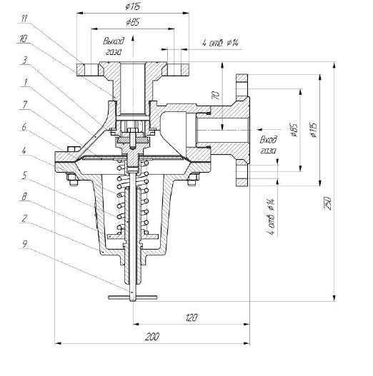
Device and principle of operation:
The aluminum body 1 (see figure) is made in the form of a truncated cone with a flange, a seat and two holes with a 2-inch cylindrical pipe thread. Valve 3 with a rubber seal closes the seat. The valve is assembled with a membrane 6, which is rigidly fixed between the valve 3 and the plate 7, as well as between the body 1 and the cover 2.
Diaphragm plate 7 and plate 8 adjusting screw 5 clamp the spring 4. The latter determines the setting of the valve 3 to the pressure within the specified limits. The force of the spring is changed by the movement of the lower plate 8. This movement is due to the rotation of the adjusting screw 5.
From the network, through the inlet pipe of the housing, gas enters the supra-membrane cavity. In steady-state conditions, the controlled gas pressure is balanced within the specified limits by the adjusted spring. In this case, the valve is hermetically closed.
When the gas pressure in the network (also in the supra-membrane cavity) exceeds the setting limit, the membrane 6, overcoming the forces of the spring 4, will lower together with the valve 3. Thus, the gas outlet to the atmosphere through the outlet pipe will be open.
The gas is discharged until the pressure in the network falls below the set one. Further, under the action of spring 4, valve 3 will close.
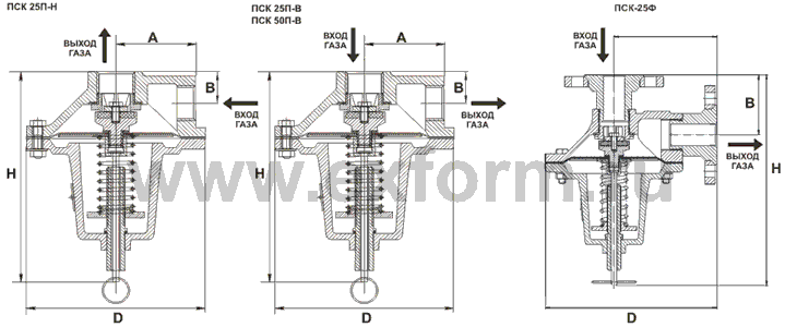
Safety relief valves PSK-25P-N (V):
1 - case; 2 - cover; 3 - valve with a guide; 4 - spring; 5 - an adjusting screw; 6 - membrane; 7 - plate; 8 - spring plate
Safety relief valves PSK 25 are membrane-type devices and are designed to discharge gas into the atmosphere when the pressure (in the network or tank) rises above the permissible limit and are installed on gas pipelines and gas control stations of low, medium and high pressure.
Connection to the pipeline - coupling (GOST 6357) or flange.
PSK valves with nominal size DN 25
produced in several types:
- relief valves low pressure triggering - PSK-25-P-N;
- high pressure relief valves - PSK-25-P-V.
Relief valves PSK 25 - technical characteristics:
| Name | Conditional pass | Regulation limit, kPa | Bandwidth |
| PSK-25-P-N | 25 mm | 2,0 -0,1 - 75,0 +7,5 | not less than 120 m 3 / h |
| PSK-25-P-V | 25 mm | 60,0 -6,0 - 750,0 +75,0 | not less than 1000 m 3 / h |
Relief valves PSK 25 - technical parameters:
| Parameter | PSK-25 | PSK-25F |
| Nominal bore, DN, mm | 25 (1"") | 25 (1"") |
| Valve setting range | from 2 to 750 kPa | from 2 to 750 kPa |
| Body material | aluminum AK 7ch | aluminum AK 7ch |
| Workspace | natural gas GOST 5542 |
natural gas GOST 5542 |
| Ambient temperature | from -40 o C to +45 o C | from -40 o C to +45 o C |
| Overall dimensions, no more: - D, mm - H, mm - A, mm - B, mm |
160 210 80 30 |
200 250 120 70 |
| Product weight, no more | 2.34 kg | 4.85 kg |
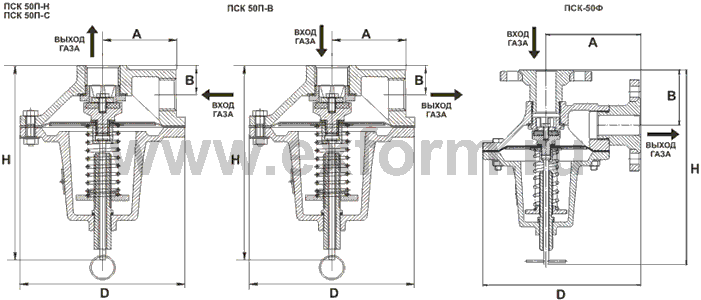
RELIEF VALVES PSK-50
 Safety relief valves PSK 50 are devices of the membrane type and are designed to discharge gas into the atmosphere when the pressure (in the network or in the tank) rises above the permissible limit and are installed on gas pipelines and gas control stations of low, medium and high pressure. Connection to the pipeline - coupling (GOST 6357) or flange.
PSK valves with nominal bore DN 50 are produced in several types:
- low pressure relief valves - PSK-50P-N / 20;
- relief valves of medium pressure of response - PSK-50-P-S / 50;
- relief valves of medium pressure of response - PSK-50-P-S / 125;
- high pressure relief valves - PSK-50-P-V / 1000.
Relief valves PSK 50 - technical characteristics:
| Name | Conditional pass | Regulation limit, kPa | Bandwidth |
| PSK-50P-N / 20 | 50 mm | 2,0 -0,1 - 20,0 +2,0 | not less than 200 m 3 / h |
| PSK-50P-S / 50 | 50 mm | 20,0 -2,0 - 50,0 +5,0 | not less than 440 m 3 / h |
| PSK-50P-S / 12 5 | 50 mm | 50,0 -5,0 - 125,0 +12,5 | not less than 1100 m 3 / h |
| PSK-50P-V / 1000 | 50 mm | 125,0 -12,5 - 1000,0 +100 | not less than 5600 m 3 / h |
Relief valves PSK 50 - technical parameters:
| Parameter | PSK-50 (coupling) | PSK-50F (flanged) |
| Nominal bore, DN, mm | 50 (2"") | 50 (2"") |
| Valve setting range | from 2 to 1000 kPa | from 2 to 1000 kPa |
| Body material | aluminum AK 7ch | aluminum AK 7ch |
| Workspace | natural gas GOST 5542 |
natural gas GOST 5542 |
| Ambient temperature | from -40 o C to +45 o C | from -40 o C to +45 o C |
| Overall dimensions, no more: - D, mm - H, mm - A, mm - B, mm |
220 240 88 43 |
260 300 149 104 |
| Product weight, no more | 4.25 kg | 10.04 kg |
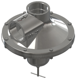
VALVE DEVICE
The external view of the PSK type valves is shown in the figure.The valve body is made in the form of a truncated cone with a flange, a seat and two holes with a cylindrical pipe thread 1 inch - version PSK-25P, 2 inches - version PSK-50P or with metric threadМ36х1,5 - execution of PSK-25PF and М56х2 - execution of PSK-50PF. The seat is closed by the valve pos. 3 with rubber seal. The valve is assembled with a diaphragm pos. 6, which is rigidly fixed between the valve and the plate, pos. 7. In turn, the membrane is fixed between the body pos. 1 and cover pos. 2.
Spring pos. 4 is clamped between the diaphragm plate and the stop pos. 8. By turning the adjusting screw pos. 5 moves the stop pos. 8, thus changing the force of the spring, which determines the adjustment of the valve to the pressure within the specified limits.
To check the operability, the valve is equipped with a forced opening mechanism, which is driven by the thrust pos. 9.
VALVE OPERATING PRINCIPLE
Gas from the network enters the valve cavity through the inlet of the body.In steady state conditions, the controlled gas pressure within the set limits is balanced by the adjusted spring, and the valve is hermetically closed.
When the gas pressure in the network (also in the valve cavity) exceeds the setting limit, the diaphragm, overcoming the spring forces, will lower together with the valve, thereby opening the gas outlet to the atmosphere through the discharge pipe.
The gas will be released until the pressure in the network drops below the set value, after which the valve will close under the action of the spring.
To test the valve's functionality, pull the pull rod of the forced opening mechanism. This opens the valve. Repeat the operation 3 - 4 times.
PRICE, PRODUCTION TIME, DELIVERY TERMS
The price for PSK-25 and PSK-50 valves is provided upon an official request to our company. The production time for relief valves does not exceed 20 days. Delivery is carried out to all regions of the Russian Federation, as well as to the territory of the CIS countries by any means of transport.Guarantee period operation - 12 months from the date of putting the product into operation, but not more than 18 months from the date of manufacture.
The assigned service life of the Valve is 30 years.