Control and measuring devices. See what "Manometer" is in other dictionaries
Principle of operation
The principle of operation of the pressure gauge is based on balancing the measured pressure by the force of elastic deformation of a tubular spring or a more sensitive two-plate membrane, one end of which is sealed in a holder, and the other is connected through a rod to a tribco-sector mechanism that converts the linear movement of an elastic sensing element into a circular movement of the pointer.
Varieties
The group of devices measuring excess pressure includes:
Pressure gauges - devices measuring from 0.06 to 1000 MPa (Measure excess pressure - the positive difference between absolute and barometric pressure)
Vacuum gauges - devices measuring vacuum (pressure below atmospheric pressure) (up to minus 100 kPa).
Manometers - manometers measuring both excess (from 60 to 240,000 kPa) and vacuum (up to minus 100 kPa) pressure.
Pressure gauges - manometers of small excess pressure up to 40 kPa
Traction gauges - vacuum gauges with a limit of up to minus 40 kPa
Traction pressure gauges - pressure and vacuum gauges with extreme limits not exceeding ± 20 kPa
Data are given according to GOST 2405-88
Most domestic and imported pressure gauges are manufactured in accordance with generally accepted standards, in this regard, pressure gauges various brands replace each other. When choosing a pressure gauge, you need to know: the measurement limit, the diameter of the case, the accuracy class of the device. The location and thread of the fitting are also important. These data are the same for all devices manufactured in our country and Europe.
There are also pressure gauges that measure absolute pressure, that is, gauge pressure + atmospheric
An instrument that measures atmospheric pressure is called a barometer.
Gauge types
Depending on the design, the sensitivity of the element, there are liquid, deadweight, deformation pressure gauges (with a tubular spring or a membrane). Pressure gauges are divided into accuracy classes: 0.15; 0.25; 0.4; 0.6; 1.0; 1.5; 2.5; 4.0 (the lower the number, the more accurate the instrument).
Low pressure gauge (USSR)
Types of pressure gauges
By appointment, pressure gauges can be divided into technical - general technical, electrocontact, special, self-recording, railway, vibration-resistant (glycerin-filled), ship and reference (exemplary).
General technical: designed to measure liquids, gases and vapors that are not aggressive to copper alloys.
Electrocontact: they have the ability to adjust the measured medium, due to the presence of an electrocontact mechanism. The EKM 1U can be called a particularly popular device of this group, although it has long been discontinued.
Special: oxygen - must be degreased, because sometimes even a slight contamination of the mechanism in contact with pure oxygen can lead to an explosion. Often produced in cases blue color with the designation on the dial O2 (oxygen); acetylene - do not allow copper alloys in the manufacture of the measuring mechanism, since upon contact with acetylene there is a danger of the formation of explosive acetylene copper; ammonia-should be corrosion-resistant.
Reference: having a higher accuracy class (0.15; 0.25; 0.4), these devices serve to test other pressure gauges. Such devices are installed in most cases on deadweight pressure gauges or any other installations capable of developing the required pressure.
Ship pressure gauges are designed for operation in the river and sea fleet.
Railway: designed for operation on railway transport.
Self-recording: pressure gauges in the case, with a mechanism that allows you to reproduce the graph of the pressure gauge on graph paper.
thermal conductivity
Thermal conduction pressure gauges are based on the decrease in the thermal conductivity of a gas with pressure. These pressure gauges have a built-in filament that heats up when current is passed through it. A thermocouple or resistance temperature sensor (DOTS) can be used to measure the temperature of a filament. This temperature depends on the rate at which the filament gives off heat to the surrounding gas and thus on the thermal conductivity. Often used is the Pirani gauge, which uses a single platinum filament as both the heating element and the DOTS. These pressure gauges give accurate readings between 10 and 10 −3 mmHg. Art., but they are quite sensitive to chemical composition measured gases.
two filaments
One wire coil is used as a heater, while the other is used to measure temperature through convection.
Pirani pressure gauge (one thread)
The Pirani pressure gauge consists of a metal wire open to the measured pressure. The wire is heated by the current flowing through it and cooled by the surrounding gas. As the gas pressure decreases, the cooling effect also decreases and the equilibrium temperature of the wire increases. Wire resistance is a function of temperature: by measuring the voltage across the wire and the current flowing through it, the resistance (and thus gas pressure) can be determined. This type of pressure gauge was first designed by Marcello Pirani.
Thermocouple and thermistor gauges work in a similar way. The difference is that a thermocouple and a thermistor are used to measure the temperature of the filament.
Measuring range: 10 −3 - 10 mmHg Art. (roughly 10 −1 - 1000 Pa)
Ionization manometer
Ionization gauges are the most sensitive measuring instruments for very low pressures. They measure pressure indirectly through the measurement of ions formed when the gas is bombarded with electrons. The lower the gas density, the fewer ions will be formed. The calibration of an ion manometer is unstable and depends on the nature of the gases being measured, which is not always known. They can be calibrated by comparison with McLeod pressure gauge readings, which are much more stable and independent of chemistry.
Thermoelectrons collide with gas atoms and generate ions. The ions are attracted to an electrode at a suitable voltage, known as a collector. The collector current is proportional to the ionization rate, which is a function of the pressure in the system. Thus, measuring the collector current makes it possible to determine the pressure of the gas. There are several subtypes of ionization gauges.
Measuring range: 10 −10 - 10 −3 mmHg Art. (roughly 10 −8 - 10 −1 Pa)
Most ion gauges fall into two categories: hot cathode and cold cathode. The third type, the rotating rotor pressure gauge, is more sensitive and expensive than the first two and is not discussed here. In the case of a hot cathode, an electrically heated filament creates an electron beam. The electrons pass through the pressure gauge and ionize the gas molecules around them. The resulting ions are collected at the negatively charged electrode. The current depends on the number of ions, which in turn depends on the pressure of the gas. Hot cathode pressure gauges accurately measure pressure in the range of 10 −3 mmHg. Art. up to 10 −10 mm Hg. Art. The principle of the cold cathode gauge is the same, except that the electrons are generated in the discharge by the high voltage electrical discharge created. Cold cathode pressure gauges accurately measure pressure in the range of 10 −2 mmHg. Art. up to 10 −9 mm Hg. Art. Calibration of ionization gauges is very sensitive to structural geometry, gas chemistry, corrosion, and surface deposits. Their calibration may become unusable when turned on at atmospheric and very low pressures. The composition of a vacuum at low pressures is usually unpredictable, so a mass spectrometer must be used simultaneously with an ionization manometer for accurate measurements.
hot cathode
A Bayard-Alpert hot cathode ionization gauge usually consists of three electrodes operating in triode mode, where the filament is the cathode. The three electrodes are the collector, filament and grid. The collector current is measured in picoamps with an electrometer. The potential difference between the filament and ground is typically 30 volts, while the grid voltage under constant voltage is 180-210 volts, if there is no optional electron bombardment, through heating the grid, which can have a high potential of approximately 565 volts. The most common ion manometer is the Bayard-Alpert hot cathode with a small ion collector inside the grid. A glass casing with an opening to the vacuum may surround the electrodes, but this is usually not used and the pressure gauge is built into the vacuum device directly and the contacts are led out through a ceramic plate in the wall of the vacuum device. Hot cathode ionization gauges can be damaged or lose calibration if they are turned on at atmospheric pressure or even low vacuum. Hot cathode ionization gauges always measure logarithmically.
The electrons emitted by the filament move forward and backward several times around the grid until they hit it. During these movements, some of the electrons collide with gas molecules and form electron-ion pairs (electron ionization). The number of such ions is proportional to the density of gas molecules multiplied by the thermionic current, and these ions fly to the collector, forming an ion current. Since the density of gas molecules is proportional to pressure, the pressure is estimated by measuring the ion current.
The low pressure sensitivity of hot cathode gauges is limited by the photoelectric effect. The electrons hitting the grid produce X-rays which produce photoelectric noise in the ion collector. This limits the range of older hot cathode gauges to 10 −8 mmHg. Art. and Bayard-Alpert to approximately 10 −10 mm Hg. Art. Additional wires at the cathode potential in the line of sight between the ion collector and the grid prevent this effect. In the extraction type, the ions are not attracted by the wire, but by the open cone. Since the ions cannot decide which part of the cone to hit, they pass through the hole and form an ion beam. This ion beam can be transferred to a Faraday cup.
cold cathode
There are two types of cold cathode gauges: the Penning gauge (introduced by Max Penning), and the inverted magnetron. The main difference between them is the position of the anode relative to the cathode. None of them have a filament, and each of them requires voltages up to 0.4 kV to function. Inverted magnetrons can measure pressures up to 10–12 mm Hg. Art.
Such gauges cannot work if the ions generated by the cathode recombine before they reach the anode. If average length the free path of the gas is less than the dimensions of the manometer, then the current on the electrode will disappear. The practical upper limit of the measured pressure of the Penning manometer is 10 −3 mm Hg. Art.
Similarly, cold cathode gauges may fail to turn on at very low pressures, since the near absence of gas makes it difficult to set the electrode current - especially in a Penning gauge, which uses an auxiliary symmetrical magnetic field to create ion trajectories on the order of meters. In ambient air, suitable ion pairs are formed by exposure to cosmic radiation; measures have been taken in the Penning gauge to facilitate the installation of the discharge path. For example, the electrode in a Penning gauge is usually tapered precisely to facilitate field emission of electrons.
Service cycles for cold cathode gauges are generally measured in years, depending on gas type and pressure in which they work. Using a cold cathode gauge in gases with significant organic components, such as pump oil residues, can result in the growth of thin carbon films within the gauge, which eventually short out the gauge electrodes, or prevent discharge path generation.
Application of pressure gauges
Pressure gauges are used in all cases where it is necessary to know, control and regulate pressure. Most often, pressure gauges are used in thermal power engineering, at chemical, petrochemical enterprises, and food industry enterprises.
Color coding
Quite often, the cases of pressure gauges used to measure the pressure of gases are painted in various colors. So the pressure gauges blue color housings are designed to measure oxygen pressure. Yellow housings have pressure gauges for ammonia, white - for acetylene, dark green - for hydrogen, grayish green - for chlorine. Manometers for propane and other combustible gases have a red case. The black body has pressure gauges designed to work with non-combustible gases.
see also
- Micromanometer
Notes
Links
| This article or section needs revision. |
Manometers are instruments used to measure pressure. Since they are used in many processes, it is difficult to imagine a modern technological cycle in which they would not be used. The scope of their application is quite wide: from measuring pressure in boiler rooms to gas pipelines, in which constant pressure is one of the guarantees of continuous operation.
The manometer is by far the most common instrument for measuring pressure. The principle of its operation is based on balancing the pressure with the force of the membrane.
The accuracy class of the pressure gauge is measured on a scale of 0.2 and higher, and the lower the value, the more accurate the device. Manometers are of several types:
If you count the pressure from the absolute zero point, then you need a device that can cope with this task. One such instrument is the absolute pressure gauge.
Separate story with atmospheric pressure. It is measured with a barometer. Pressure difference in different environments measured with differential pressure gauges, or differential pressure gauges. To measure positive and negative pressure, there are pressure gauges. Pressure values close to each other are measured by micromanometers.
Types of pressure gauges
Pressure gauges are divided into: working, general technical and general industrial.
This is the most common group of measuring instruments. With their help, the pressure difference between the pressure of gases and liquids, as well as the excess and vacuum pressure of steam, gases and liquids is measured. These pressure gauges are best adapted to work on industrial equipment. The accuracy of their measurement ranges from 1 to 1.5; 2.5.
General technical pressure gauges successfully work in boiler houses, gas pipelines and heat supply systems. Gauges are both pointer and digital. On digital pressure gauges, information about pressure is displayed on an electronic display. The scope of such pressure gauges is quite wide - from a simple pressure gauge in an individual boiler room to a pressure gauge on an industrial gas pipeline.
Exemplary pressure gauges
Such manometers measure the pressure of liquids or gases with increased accuracy. These devices allow you to measure pressure in very accurate numbers of the class. For spring pressure gauges, this is: 0.16; 0.25, and for cargo piston - 0.05; 0, 2. The measurement accuracy of these manometers is given by a special “clean” processing and fitting of gears and working surfaces.
Electrocontact pressure gauges
Electrocontact manometers control the threshold values of pressure, and also signal them. Such pressure gauges measure the excess pressure of gases and liquids.
Their work also includes monitoring and controlling the electrical circuit after certain periods of time. The connection of the pressure gauge and the head mechanism is carried out by means of a contact group. In view of the fact that excess pressure carries a certain danger, explosion-proof pressure gauges are also produced.
Special pressure gauges
Special pressure gauges are used to measure a certain type of gas: ammonia, acetylene, oxygen, hydrogen. The scope of such pressure gauges is quite wide.
Such devices measure the pressure of only one type of gas. For distinction, a certain letter is placed on the pressure gauge body, it is painted in a special color, and its scale indicates the value of the gas. Manometers for measuring ammonia pressure are bright yellow,
It has the letter "A" on it. The accuracy classes of such pressure gauges are the same as those of general technical ones.
Self-recording pressure gauges
Such pressure gauges not only measure pressure, but also record its readings on chart paper. Can record up to three meanings simultaneously. They are used both in energy and in industry.
Ship pressure gauges
Marine pressure gauges are used on ships and submarines. They measure the pressure of liquids (both gauge and vacuum). They also measure the pressure of gases and steam. They are produced in a special moisture- and dust-proof case.
Railway pressure gauges
Unlike ship pressure gauges, railway pressure gauges measure excess and vacuum pressure on land, and more precisely, in railway transport.
Sensors and transducers
These devices do not measure, but convert pressure into a signal. Such signals can be of any kind, from electrical to pneumatic. The signal is converted by various methods. Such sensors measure vacuum, gauge, absolute, differential and hydrostatic pressure. And there are also transducers for measuring pressure differences. These pressure transmitters differ in frequency range, accuracy, range limit and weight. DM5007 sensors are equipped with a digital display. They differ high precision measurement and reliability.
In Sapphire-22MPS sensors, a strain gauge is used to measure pressure, which changes its resistance when the sensitive element is deformed due to pressure. Such a sensor is equipped with a digital indicator.
The signal received from the strain gauge is recoded at the output into a unified electrical signal. The Sapphire-22MPS sensor is equipped with a thermal compensation system and microprocessor signal processing. This allows you to increase the accuracy of measurements, simplifies the installation of zero, measurement range and measurement limits within subranges. Such converters are widely used in process control systems, gas industry and nuclear power facilities.
Manometric thermometer
Such a device works due to the relationship between the temperature and pressure of the medium being measured. These pressure gauges are used to measure the temperature of a liquid or gas in closed system. Manometric thermometers are divided into condensation and gas.
Condensation thermometers are marked TKP
Electrocontact manometric thermometers are equipped with arrows that set the response thresholds. When the upper or lower threshold is reached, the alarm group closes. Such manometers are also called signal.
Http-equiv="Content-Type" />
Pressure measuring instruments
Sheshin E.P. Fundamentals of vacuum technology: Tutorial. - M.: MIPT, 2001. - 124 p.
An integral part of any vacuum system is equipment for measuring the pressure of a rarefied gas. The pressure area used in modern vacuum technology is 10 5 - 10 -12 Pa. Measurement of pressures in such a wide range, of course, cannot be provided by one instrument. In the practice of measuring the pressure of rarefied gases, various types of transducers are used, which differ in the principle of operation and accuracy class.
Instruments for measuring total pressures in vacuum technology are called vacuum gauges and usually consist of two parts - a manometric transducer and a measuring unit. According to the measurement method, vacuum gauges can be divided into absolute and relative. The readings of absolute instruments do not depend on the type of gas and can be pre-calculated.
These pressure gauges measure pressure, which is the force of molecules hitting a surface. At low pressures, direct measurement of the pressure force is impossible due to its smallness. In devices for relative measurements, the dependence of the parameters of some physical processes occurring in vacuum on pressure is used. These instruments need to be calibrated according to reference instruments. Vacuum gauges measure the pressure of gases present in a vacuum system. On fig. 3.1. operating pressure ranges shown various types vacuum gauges.
3.1. Absolute gauges
Hydrostatic U-shaped vacuum gauge, appearance which is shown in Fig. 3.2 is a glass U-tube filled with mercury or some other low vapor pressure liquid such as vacuum oil. Both elbows of the tube are interconnected by a three-way glass cock. In the position of the crane shown in the figure, both knees communicate with each other. The right knee is connected to an auxiliary pump, which creates a vacuum of 10–1–1 Pa.
|
hydrostatic |
||||||||
|
__deformation___ |
||||||||
|
______thermal _______ |
||||||||
|
__compression___ |
||||||||
|
______ radioisotope _______ |
||||||||
|
_electronic ionization_ |
||||||||
|
_________ magnetic electric discharge ___________ |
||||||||
Rice. 3.1. Operating pressure range measured by vacuum gauges
During the measurement, this pressure is assumed to be zero. When the valve handle is turned 180˚, both knees are separated from each other, and the left knee communicates with the vessel in which the pressure must be measured. The pressure is calculated by the formula
where r- density of the working fluid; g- free fall acceleration for a given area; h- the difference between the levels of the working fluid in both knees of the vacuum gauge.
The range of pressures measured with a mercury vacuum gauge is 102 - 105 Pa (1 - 100 Torr), with an oil gauge - 1 - 5 × 10³ Pa (0.01 - 50 Torr).
The McLeod compression vacuum gauge is schematically shown in fig. 3.3. It is called compression because it compresses (compresses) the gas in a sealed capillary. The main elements of the vacuum gauge are a sealed capillary To 1 with vessel V 1 , the total volume of which up to the point a during the calibration process is determined with great accuracy, and the reference capillary To 2, the diameter of which, like that of the sealed capillary, must be constant along the entire length and equal to the diameter of the sealed capillary.
|
Rice. 3.2. U-shaped |
Rice. 3.3. compression |


To make a measurement, lower the mercury level in the vacuum gauge below the point a. In this case, the measuring capillary To 1 communicates with the system in which the pressure is to be measured. With a subsequent increase in the level of mercury in the vacuum gauge, a portion of gas equal to the total volume of the measuring capillary To 1 and vessel V 1, at a pressure equal to the gas pressure in the system, will be cut off and compressed in a sealed capillary. According to the Boyle–Mariotte law, the product of the pressure of a certain portion of gas and the volume occupied by it is a constant value:
Initial volume V 1 known, final volume V 2 is easy to calculate from the known capillary diameter K1, and the pressure P 2 is determined by the difference in mercury levels h in the measuring K 1 and comparative To 2 capillaries. Then, according to the formula (3.2.), the desired pressure in the vacuum system is easily calculated R 1.
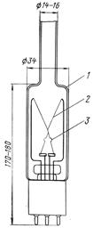
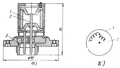
Deformation vacuum gauges as a sensitive element have a sealed elastic partition that can be deformed under the action of a pressure difference applied to it. The most widespread vacuum gauges of the MVP type, the device of which is schematically shown in fig. 3.4. The elastic sensitive element is a tube of elliptical section, coiled into a spiral. The tube, under the action of atmospheric pressure, when pumping out the inner cavity, twists due to different radii of curvature, and, consequently, the areas of the outer and inner surface tubes. One end of the tube is connected to the vacuum system with a fitting, the other, sealed, the end of the tube is connected to the pointer of the device through a system of levers. The angle of twist of the elastic element and, accordingly, the angle of rotation of the arrow are proportional to the pressure difference inside and outside the elastic element.
The deformation vacuum gauge has a number of advantages: convenience in working with a vacuum gauge, immediacy of reading, inertia-free operation. In addition to this, he has significant disadvantage: dependence of vacuum gauge readings on barometric pressure. The pressure area measured by a deformation vacuum gauge is 5 10 2 - 105 Pa (~ 3-750 Torr). In addition to the described, there are other types of deformation gauges, such as membrane gauges, which are available for different ranges of measured pressures. 
Rice. 3.4. Deformation vacuum gauge:
1 - pipe of elliptical section;
2 - arrow; 3 - gear sector;
4 - connecting fitting.
3 .2. Thermal gauges
The action of thermal vacuum gauges is based on the dependence of the thermal conductivity of a gas on pressure. The main elements of any thermoelectric manometric transducer are the filament (with a constant temperature and high heat capacity) and the body of the device. At a constant electric power supplied to the filament Q el., the temperature of the filament depends on the pressure. In the stationary state at a steady temperature of the filament, the power balance takes place:
![]() , (3.3)
, (3.3)
where Q k - heat sink power according to structural elements pressure gauge; Q m is the power removed from the thread by molecules colliding with it; Q l is the power removed by radiation.
Since with increasing pressure the thermal conductivity of the gas increases, then the Q m. Therefore, when Q el = const the equilibrium temperature of the filament increases with decreasing pressure (if l 0
>> d). Therefore, the temperature of the thread is measured in a thermal manometer and the measurement results are calibrated in units of pressure.
On fig. 3.5, 3.6 shows the designs of the most common types of thermal pressure gauges and their connection schemes. Transducers, depending on the method of measuring temperature, are divided into thermocouple and resistance transducers.
|
|
|

Rice. 3.5. Manometric resistance transducer PMT-6:
a) design; b) measurement scheme
1 - body; 2 - filament
The housing of the PMT-6 converter (Fig. 3.5a) is made of of stainless steel, the filament is made of tungsten wire with a diameter of 10 microns and a length of 80 mm. The manometer is in operation constant temperature thread equal to 220 ºС. In this case, the resistance of the thread is 116.5 ohms. The pressure gauge is included in one of the arms of the bridge (Fig. 3.5b). A change in the signal, indicating a change in pressure, is recorded by a pointer device. When the pressure changes from 10–2 to 30 Torr, the filament filament current changes from 4 to 52 mA, and the voltage from 0.5 to 6 V.
In the pressure range from 1 to 10-3 Torr, thermocouple manometers are most widely used (Fig. 3.6).
The filament in this gauge performs only the function of a heat source. The lamp is in operation direct current incandescence, which is regulated by tuning the ballast resistor. The pressure is estimated by EMF. thermocouples (Fig. 3.7). The filament current is 110–135 mA and is selected in such a way that the millivoltmeter needle exactly matches the hundredth division of the scale.
 |
|
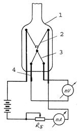
Fig 3.6. Thermocouple pressure transducer PMT-2:
a) design; b) measurement scheme.
1 - body; 2 - filament; 3 - thermocouple; 4 - power input
At pressures below 10–3 Torr, the pressure gauge readings reach an asymptotic limit of 10 mV (100 divisions). At these pressures, the heat removal through the gas is negligibly small, and all the input power is spent on radiation (~ 63%) and heat removal through the bushings (~ 37%).
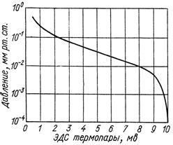
Rice. 3.7. Calibration curve of thermocouple pressure gauge PMT-2
The upper limit of thermocouple manometers is determined by two phenomena: 1) at high pressure, the condition is violated, and the thermal conductivity of the gas ceases to depend on pressure; 2) at high pressure, intense molecular heat removal greatly reduces the temperature of the filament, reduces the temperature difference between the filament and the case, and leads to a loss of sensitivity.
At a current of about 120 mA, the PMT-2 lamp has an upper pressure limit of about 10–1 Torr. To combat the loss of sensitivity at high pressure, it is enough to increase the temperature of the filament, i.e. increase the current. At a current of 250–300 mA, the PMT-2 lamp can measure pressures in the range of 10–1–1 Torr. For this range exact value the filament current is selected at atmospheric pressure, i.e. the calibration curve is tied to the upper right asymptotic limit of the manometer. The sensors of thermal vacuum gauges are not afraid of atmospheric breakthrough and have an almost unlimited service life.
3.3. Electronic ionization gauges
The principle of operation of the electronic converter is based on direct proportionality between pressure and ionic current, formed as a result of ionization of residual gases by thermoelectrons.
There are two schemes of the electronic converter: with internal and external collector. The main elements of an electronic ionization gauge transducer are a direct filament, an anode-grid and an ion collector. The cathode can be located both in the center of the grid-anode, for example, in the PMI-3-2 and PMT-2 converters (Fig. 3.8a), and on the outside, for example, in the PMI-12-8 and IM-12 converters ( Fig. 3.8b). In the first case, the collector covers the anode; in the second - the collector is located along the axis of the transducer.
Rice. 3.7. Structural schemes of electronic ionization
converters:
a) with an external collector (PMI-2; PMI-3-2);
b) with an internal manifold (IM-12; PMI-12-8);
1 - collector; 2 - grid-anode; 3 - direct filament cathode
The electric potentials of the electrodes are such that they create for electrons an accelerating potential difference in the space between the anode and cathode and a decelerating potential difference in the space between the anode and the ion collector, and the decelerating potential difference is greater than the accelerating potential difference. Usually the collector has a zero potential, the anode is high positive, the cathode is a small positive potential. The power supply of the manometric transducer is carried out by the measuring unit of the vacuum gauge.
Electronic ionization gauge transducer operates as follows. The cathode heated by direct current transmission emits electrons. The electrons are accelerated in the space between the cathode and anode. Most of the electrons fly through the anode-grid, falling into the moderating electric field. Since the decelerating potential difference is greater than the accelerating potential difference, the electrons, not reaching the ion collector, change the direction of motion. Then, acquiring speed towards the anode, the electrons again fly through the anode-grid, slow down near the cathode, and again go to the anode. Thus, the electrons oscillate around the anode.
On their way, the electrons ionize the gas. Positive ions formed in the space between the anode and the ion collector are attracted by the latter. At a constant current of electron emission (the emission current in the vacuum gauges under consideration is set at 5 mA.) with a constant number of electrons oscillating near the anode, the number of ionization events, i.e. the number of ions formed will be proportional to the concentration of gas molecules in space, i.e. pressure. Thus, the collector ion current serves as a measure of gas pressure. The electronic transducer has a different sensitivity to different gases, since the ionization efficiency depends on the type of gas.
If the transducer was calibrated in air, but is used to measure the pressure of other gases, then it is necessary to take into account the relative sensitivity R, which is presented in table 3.1.
In this case, the gas pressure is defined as
![]() .
(3.4)
.
(3.4)
Table 3.1
Relative sensitivity of transducers
|
Gas |
||||||||||
Ionization manometers have a pumping action. For PMI-2 lamps, the ion pumping speed is approximately 0.01 l/s. Upper limit electronic pressure gauge(10–2 Torr) is due to fast sputtering of the tungsten cathode. In addition, at high pressure, the linear dependence of the current on pressure is violated, when the mean free path of an electron in the volume of the device becomes less than the distance between the electrons. An increase in the upper limit of measurement can be achieved through the use of special air-resistant iridium cathodes, as well as by reducing the distance between the electrodes.
The lower measurement limit is determined by the background currents in the collector circuit. Background currents arise either as a result of soft X-ray radiation from the anode grid, or, as a consequence, field emission of the collector and ultraviolet radiation of the filament cathode, accompanied by the escape of photoelectrons from the collector. X-ray radiation of the anode grid is the result of its bombardment with electrons. The autoelectronic emission of the collector appears under the action of a potential difference of 200–300 V between the collector and the anode grid. In the PMI-2 lamp, the cylindrical collector captures almost all the x-ray radiation of the grid; therefore, the lower measurement limit for manometers with an external collector of the PMI-2 type is 10–7 Torr.
Background currents have the same direction as ion currents and have the same effect on the measuring instruments. To reduce background currents, a converter with an axial collector was proposed (Fig. 3.8b), where the cathode and collector were reversed, which significantly reduced the solid angle in which the x-ray radiation from the grid hits the collector, which expanded the lower measurement limit to 10–10 Torr.
To accurately measure low pressure, it is necessary to degas the anode by passing an electric current through it. Transducers should be degassed at low pressure in the system 20–40 min before pressure measurement. It is not necessary to degas the converter at high pressures, since in this case the relative error caused by sorption-desorption phenomena is usually small. Moreover, outgassing and, as a rule, heating at high pressures increase the intensity chemical processes on the electrodes, which leads to an accelerated failure of the converter. In this regard, it should be considered incorrect practice to start outgassing immediately after turning on the converter, when a high vacuum has not yet been reached in the installation.
Pressure measurements with gauge transducers open type, whose electronic system is located directly in the evacuated vessel, gives a better correspondence with the true pressure in the system than when using transducers closed type.
For a more accurate judgment of the pressure in the system at low pressures, based on the readings of the vacuum gauge, it is necessary to take into account the composition of the gas in order to correct for the different sensitivity of the transducer to different gases. It should be remembered that gases such as oxygen or water vapor containing oxygen cause a decrease in the emission current, poisoning the cathode. Conversely, hydrocarbon vapors cause a sharp increase in the emission current. Therefore, immediately before the measurement, always check the emission current.
3.4. Magnetic gas discharge gauges
The principle of operation of magnetic converters is based on the dependence of the current of a self-sustaining gas discharge in crossed by a magnet and electric fields from pressure:
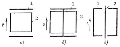
Rice. 3.8. Electronic systems of magnetic transducers:
a) Penning cell; b) magnetron; c) inverse magnetron;
1 - cathodes; 2 - anodes
There are several types of electrode systems that maintain an independent gas discharge under high and ultrahigh vacuum.
The Penning cell (Fig. 3.9) consists of two disk cathodes 1 and a cylindrical anode 2; in the magnetron converter (Fig. 3.9b), in contrast to the Penning cell, the cathodes are interconnected by a central rod; in an inverse magnetron converter (Fig. 3.9c), the central rod acts as an anode, and the outer cylinder becomes a cathode.
All electrodes are in a constant magnetic field. A positive voltage of 2–6 kV relative to the cathode is applied to the anode, the cathode is grounded and connected to the DC amplifier input. A strong magnetic field serves to increase the length of the electron path and thereby maintain the discharge and increase the degree of gas ionization. The strength of the discharge current in such devices is a measure of the pressure in the system.
Recently, inverse-magnetron vacuum gauges are becoming more and more common. As an example, we give the design of the PMM-32-1 inverse magnetron converter (Fig. 3.10)
Electronic transducer system on the connection flange with a metal seal with a nominal bore of 50 mm. Cathode 1 is a cylinder with closed ends. Rod anode 2 passes along the cathode axis through holes in its end surfaces. The entire electrode system in the body of the device is placed in an axial magnetic field. A high voltage is applied to the anode. The input of the DC amplifier is connected to the cathode circuit.
Rice. 3.10. Inverse-magnetron manometric transducer PMM-32-1:
a) converter design:
1 - cathode; 2 – anode; 3 - connecting flange;
b) electron trajectory
Under the action of crossing electric and magnetic fields, free electrons formed in the discharge gap move along closed hypocycloids. When colliding with a gas molecule, an electron loses some of its energy, and its trajectory shifts closer to the anode, as shown in Fig. 3.10b. The electrons enter the anode after at least one act of gas ionization. In such gauge transducers, the discharge is maintained at pressures up to 10–12–10–11 Pa (10–14–10–13 Torr). The positive ions formed as a result of gas ionization, due to their large mass, move almost rectilinearly to the cathode, which is also an ion collector. The concentration of gas molecules in the discharge gap of the transducer is judged by the magnitude of the ion current, i.e. about the gas pressure in the system. Background currents, field emission currents in the measuring circuit of the cathode are not recorded, since they are closed in the screen-anode circuit.
The pumping speed varies for various transducers, depending on the type of gas and operating modes, in the range from 10–2 to 1 l / s, which is much more than for electronic ones. This leads to an increase in measurement errors in the presence of vacuum resistance between the transducer and the vacuum chamber. The advantage of a magnetic converter over an electronic one is higher reliability and operation due to the replacement of the incandescent cathode with a cold one, and the disadvantage is instabilities associated with fluctuations in the work function of the electrons when the cathodes are contaminated. These instabilities are especially noticeable when the transducer operates in vacuum systems with oil vapors, the decomposition products of which during ion bombardment and dielectric oil films covering the electrode surfaces can reduce the sensitivity of the transducer by several times.
The outgassing of magnetic-discharge transducers, as well as electronic ones, should be carried out at high vacuum and only if it is necessary to measure the pressure in the region of high and ultrahigh vacuum. For some time after outgassing, the converter has a strong pumping action. The error caused by the pumping action can reach several percent for open converters, and 20% or more for closed converters. Measurement error caused by outgassing has opposite sign and is usually much larger than the error caused by the pumping action of the device.
The vacuum gauge readings also depend on the state of the transducer and the tension magnetic field. Therefore, in order to avoid changing the magnetic field strength, ferromagnetic bodies should not be brought to the transducers at a distance of less than 100 mm. During operation, it is necessary to periodically monitor the leakage resistance of insulators, which cause additional background current, and it is also useful to control the magnetic field strength.
In hydraulic fracturing, the following instrumentation is used to control the operation of equipment and measure gas parameters:
- thermometers for measuring gas temperature;
- indicating and recording (self-recording) pressure gauges for measuring gas pressure;
- devices for registering pressure drop on high-speed flow meters;
- gas consumption meters (gas meters or flow meters).
All instrumentation must be subject to state or departmental periodic verification and be in constant readiness for measurements. Readiness is ensured by metrological supervision. Metrological supervision consists in constant monitoring of the condition, working conditions and correctness of instrument readings, their periodic verification, and the removal from operation of instruments that have become unusable and have not passed inspection. Instrumentation should be installed directly at the measurement site or on a special instrument panel. If the instrumentation is mounted on the instrument panel, then one instrument with switches is used to measure readings at several points.
Instrumentation is connected to gas pipelines steel pipes. Impulse tubes are connected by welding or threaded couplings. All instrumentation must have the hallmarks or seals of the Rosstandart authorities.
instrumentation with electric drive, as well as telephone sets must be explosion-proof, otherwise they are placed in a room isolated from the hydraulic distribution unit.
The most common types of instrumentation in hydraulic fracturing include the instruments discussed later in this section.
Instruments for measuring gas pressure are divided into:
- on liquid devices, in which the measured pressure is determined by the value of the balancing liquid column;
- spring devices, in which the measured pressure is determined by the amount of deformation of the elastic elements (tubular springs, bellows, membranes).
Liquid manometers are used to measure excess pressures up to 0.1 MPa. For pressures up to 10 MPa, the pressure gauges are filled with water or kerosene (at negative temperatures), and when measuring higher pressures, with mercury. Liquid pressure gauges also include differential pressure gauges (differential pressure gauges). They are used to measure pressure drop.
Differential pressure gauge DT-50(picture below), Thick-walled glass tubes are firmly fixed in the upper and lower steel blocks. At the top, the tubes are connected to trap chambers that prevent the tubes from escaping mercury in the event of an increase in maximum pressure. Needle valves are also located there, with the help of which it is possible to disconnect the glass tubes from the measured medium, purge the connecting lines, and also turn off and turn on the differential pressure gauge. Between the tubes there is a measuring scale and two pointers that can be set to the upper and lower levels of mercury in the tubes.
Differential pressure gauge DT-50
a - design; b - channel layout; 1 - valves high pressure; 2, 6 - pads; 3 - camera traps; 4 - measuring scale; 5 - glass tubes; 7 - pointer
Differential pressure gauges can also be used as ordinary pressure gauges for measuring excessive gas pressures, if one tube is led into the atmosphere, and the other into the measured medium.
Pressure gauge with single-coil tubular spring(picture below). A bent hollow tube is fixed with its lower fixed end to a fitting, with the help of which the pressure gauge is connected to the gas pipeline. The second end of the tube is sealed and pivotally connected to the rod. The gas pressure through the fitting is transmitted to the tube, the free end of which through the rod causes the movement of the sector, gear and axle. The spring hair ensures the grip of the gear wheel and the sector and the smoothness of the arrow. A shut-off valve is installed in front of the pressure gauge, which allows, if necessary, to remove the pressure gauge and replace it. Pressure gauges during operation must undergo state verification once a year. The working pressure measured by the pressure gauge should be between 1/3 and 2/3 of their scale.
Pressure gauge with single-coil tubular spring

1 - scale; 2 - arrow; 3 - axis; 4 - gear wheel; 5 - sector; 6 - tube; 7 - thrust; 8 - spring hair; 9 - fitting
Self-recording pressure gauge with a multi-turn spring (figure below). The spring is made in the form of an oblate circle with a diameter of 30 mm with six turns. Due to the large length of the spring, its free end can move by 15 mm (for single-turn pressure gauges - only by 5-7 mm), the angle of untwisting of the spring reaches 50-60 °. This design allows the use of the simplest lever transmission mechanisms and automatic recording of readings from remote transmission. When the pressure gauge is connected to the measured medium, the free end of the lever spring will turn the axis, while the movement of the levers and rod will be transmitted to the axis. A bridge is fixed on the axis, which is connected to the arrow. Change in pressure and movement of the spring through linkage are transmitted to the arrow, at the end of which a pen is installed to record the measured pressure value. The chart is rotated by clockwork.
Scheme of a self-recording pressure gauge with a multi-turn spring

1 - multi-turn spring; 2, 4, 7 - levers; 3, 6 - axes; 5 - thrust; 8 - bridge; 9 - arrow with a pen; 10 - cartogram
Float differential pressure gauges.
Float differential pressure gauges (Figure below) and narrowing devices are widely used in the gas industry. Constriction devices (diaphragms) are used to create a pressure drop. They work in conjunction with differential pressure gauges that measure the created pressure drop. At a steady gas flow rate, the total energy of the gas flow is the sum of potential energy (static pressure) and kinetic energy, i.e. velocity energy.
Before the diaphragm, the gas flow has an initial speed ν 1 in a narrow section, this speed increases to ν 2, after passing through the diaphragm, the tray expands and gradually restores its previous speed.
With an increase in the flow velocity, its kinetic energy increases and, accordingly, the potential energy, that is, the static pressure, decreases.
Due to the pressure difference Δp = p st1 - p st2, the mercury in the differential pressure gauge moves from the float chamber into the glass. As a result, the float located in the float chamber descends and moves the axis, to which the arrows of the device showing the gas flow are connected. Thus, the pressure drop across a throttle device, measured with a differential pressure gauge, can serve as a measure of gas flow.
Float differential pressure gauge

a - structural diagram; b - kinematic diagram; c - graph of changes in gas parameters; 1 - float; 2 - shut-off valves; 3 - diaphragm; 4 - glass; 5 - float chamber; 6 - axis; 7 - impulse tubes; 8 - annular chamber; 9 - pointer scale; 10 - axes; 11 - levers; 12 - pen bridge; 13 - pen; 14 - diagram; 15 - clock mechanism; 16 - arrow
The relationship between pressure drop and gas flow is expressed by the formula

where V is the volume of gas, m 3; Δp - pressure drop, Pa; K is a coefficient constant for a given aperture.
The value of the coefficient K depends on the ratio of the diameters of the aperture of the diaphragm and the gas pipeline, the density and viscosity of the gas.
When installed in a gas pipeline, the center of the diaphragm opening must coincide with the center of the gas pipeline. Diaphragm opening on the gas inlet side cylindrical shape with a conical extension to the flow outlet. The diameter of the inlet of the disk is determined by calculation. The leading edge of the disc hole must be sharp.
Normal diaphragms can be used for gas pipelines with a diameter of 50 to 1200 mm, subject to 0.05< m < 0,7. Тогда m = d 2 /D 2 где m - отношение площади отверстия диафрагмы к cross section gas pipeline; d and D are the diameters of the aperture of the diaphragm and the gas pipeline.
Normal diaphragms can be of two types: chamber and disk. To select more accurate pressure pulses, the diaphragm is placed between the annular chambers.
The plus vessel is connected to the impulse tube, which takes pressure to the diaphragm; the negative vessel is supplied with pressure taken after the diaphragm.
In the presence of gas flow and pressure drop, part of the mercury is squeezed out of the chamber into a glass (figure above). This causes the float to move and, accordingly, the arrow indicating the gas flow rate, and the pen, which marks the magnitude of the pressure drop on the diagram. The chart is driven by a clock mechanism and makes one revolution per day. The scale of the diagram, divided into 24 parts, allows you to determine the gas flow rate for 1 hour. safety valve, which separates vessels 4 and 5 in the event of a sudden pressure drop and thus prevents a sudden release of mercury from the device.
Vessels communicate with impulse tubes diaphragm through shut-off valves and an equalizing valve, which must be closed in the working position.
Bellows pressure gauges(figure below) are designed for continuous measurement of gas flow. The operation of the device is based on the principle of balancing the pressure drop by the forces of elastic deformations of two bellows, a torsion tube and helical coil springs. The springs are replaceable, they are installed depending on the measured pressure drop. The main parts of the differential pressure gauge are the bellows block and the indicating part.
Schematic diagram of a bellows differential pressure gauge

1 - bellows block; 2 - positive bellows; 3 - lever; 4 - axis; 5 - throttle; 6 - minus bellows; 7 - replaceable springs; 8 - stock
The bellows block consists of interconnected bellows, the internal cavities of which are filled with liquid. The liquid consists of 67% water and 33% glycerin. The bellows are interconnected by a rod 8. An impulse is supplied to the bellows 2 before the diaphragm, and to the bellows 6 - after the diaphragm.
Under the action of a higher pressure, the left bellows is compressed, as a result of which the liquid in it flows through the throttle into the right bellows. The rod, rigidly connecting the bottoms of the bellows, moves to the right and, through the lever, rotates the axis kinematically connected with the pointer and pen of the recording and indicating instrument.
The throttle regulates the flow rate of the liquid and thereby reduces the effect of pressure pulsation on the operation of the device.
Replaceable springs are used for the corresponding measurement limit.
Gas meters. Rotary or turbine meters can be used as counters.
In connection with the mass gasification industrial enterprises and boiler rooms, an increase in the types of equipment, it became necessary to measuring instruments with a big throughput and a significant measurement range at small overall dimensions. These conditions are more satisfied with rotary counters, in which 8-shaped rotors are used as a converting element.
Volumetric measurement in these meters is carried out due to the rotation of two rotors due to the difference in gas pressure at the inlet and outlet. The pressure drop in the meter required for the rotation of the rotors is up to 300 Pa, which makes it possible to use these meters even at low pressure. The domestic industry produces meters RG-40-1, RG-100-1, RG-250-1, RG-400-1, RG-600-1 and RG-1000-1 for nominal gas flow rates from 40 to 1000 m 3 / h and pressure not more than 0.1 MPa (in the SI system, the flow rate is 1 m 3 / h \u003d 2.78 * 10 -4 m 3 / s). If necessary, parallel installation of meters can be used.
Rotary counter RG(picture below) consists of a housing, two profiled rotors, a gear box, a gearbox, an account mechanism and differential pressure gauge. Gas through the inlet pipe enters the working chamber. In the space of the working chamber, rotors are placed, which are driven under the pressure of the flowing gas.
Scheme of a rotary counter type RG
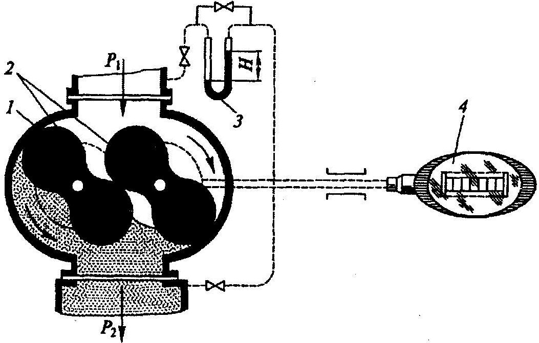
1 - counter body; 2 - rotors; 3 - differential pressure gauge; 4 - pointer of the counting mechanism
When the rotors rotate, a closed space is formed between one of them and the chamber wall, which is filled with gas. Rotating, the rotor pushes the gas into the pipeline. Each rotation of the rotor is transmitted through a box of gears and a gearbox to a counting mechanism. Thus, the amount of gas passing through the meter is taken into account.
The rotor is prepared for operation as follows:
- remove the upper and lower flanges, then wash the rotors with a soft brush dipped in gasoline, turning them with a wooden stick so as not to damage the polished surface;
- then both gear boxes and gearbox are washed. To do this, fill in gasoline (through the top plug), turn the rotors several times and drain the gasoline through the bottom plug;
- after washing, pour oil into the gear boxes, gearbox and counting mechanism, pour the appropriate liquid into the meter pressure gauge, connect the flanges and check the meter by passing gas through it, after which the pressure drop is measured;
- then they listen to the operation of the rotors (they must rotate silently) and check the operation of the counting mechanism.
During a technical inspection, they monitor the oil level in the gear boxes, gearbox and counting mechanism, measure the pressure drop, and check the meters for tight connections. Meters are installed on vertical sections of gas pipelines so that the gas flow is directed through them from top to bottom.
Turbine counters.
In these meters, the turbine wheel is driven by the gas flow; the number of revolutions of the wheel is directly proportional to the flowing volume of gas. In this case, the number of revolutions of the turbine through a reduction gear and a magnetic coupling is transmitted to a counting mechanism located outside the gas cavity, showing the total volume of gas that has passed through the device under operating conditions.