Pig-iron sewer pipe gost. Pipes pig-iron sewer and shaped parts to them. Requirements for raw materials, materials and components
GOST 6942-98
UDC 696.133:669.13:006.354 Group G21
INTERSTATE STANDARD
PIPES CAST IRON SEWER AND
FITTINGS TO THEM
Specifications
CAST IRON WASTE PIPES AND FITTINGS
OKSTU 4925 OKS 91.140.70
Introduction date 1999-01-01
Foreword
1 DEVELOPED by the Research Institute of Sanitary Engineering (Scientific Research Institute of Sanitary Engineering) of the Russian Federation
INTRODUCED by Gosstroy of Russia
2 ADOPTED by the Interstate Scientific and Technical Commission for Standardization, Technical Regulation and Certification in Construction (ISTCS) on November 12, 1998
|
State name |
Name of the public administration body for construction |
|
Republic of Armenia |
Ministry of Urban Development of the Republic of Armenia |
|
The Republic of Kazakhstan |
Committee on Housing and Construction Policy under the Ministry of Energy, Industry and Trade of the Republic of Kazakhstan |
|
Republic of Kyrgyzstan |
State Inspectorate for Architecture and Construction under the Government of the Kyrgyz Republic |
|
The Republic of Moldova |
Ministry of Territorial Development, Construction and Public Utilities of the Republic of Moldova |
|
the Russian Federation |
Gosstroy of Russia |
|
The Republic of Tajikistan |
Gosstroy of the Republic of Tajikistan |
3 INSTEAD OF GOST 6942.0-80 - GOST 6942.24-80, GOST 4.227-83.
4 ENTERED INTO EFFECT on January 1, 1999 as the state standard of the Russian Federation by the Decree of the Gosstroy of Russia dated December 31, 1998 No. 31.
1 area of use
This standard applies to cast iron sewer pipes and fittings for them intended for internal sewerage systems of buildings.
Mandatory requirements for product quality are set out in: 5.1; 5.2.2 - 5.2.4; 5.2.7; 5.2.8; 5.3.1; 5.3.2.
GOST 164-90 Height gauges. Specifications
GOST 166-89 Calipers. Specifications
GOST 1412-85 Cast iron with lamellar graphite for castings. Stamps
GOST 9812-74 Oil insulating bitumen. Specifications
GOST 15150-69 Machinery, instruments and other technical products. Versions for different climatic regions. Categories, conditions of operation, storage and transportation in terms of the impact of environmental climatic factors
GOST 18510-87 Writing paper. Specifications
GOST 26358-84 Cast iron castings. General specifications
GOST 26598-85 Containers and packaging facilities in construction. General specifications
GOST 26645-85 Castings from metals and alloys. Dimensional tolerances, weights and machining allowances.
3 Assortment
3.1 The assortment of pipes and fittings must correspond to that specified in Table 1.
Table 1
|
Name |
Nominal passages, mm |
Symbol |
||
|
graphic |
literal |
|||
|
Branch pipes |
||||
|
Compensation pipes |
|
|||
|
Adapter pipes |
|
PP-D 1 x D y |
||
|
Knees low |
||||
|
Elbows 110° and 120° |
About 110°-D y or |
|||
|
Elbows 135° |
||||
|
Elbows 150° |
||||
|
Branches-tees instrument |
OTPR-100x50 or LOTPr-100x50 |
|||
|
Straight tees |
|
TP-D y x d y |
||
|
Equal expansion tees |
|
TPK-D y x d y |
||
|
Straight low tees |
|
|||
|
Straight reducing tees |
|
TPR-100/50x100 |
||
|
Straight reducing tees low |
|
TPRN-100/50x100 |
||
|
45° and 60° oblique tees |
|
TK45°-D y x d y and TK60°-D y x d y |
||
|
Crosses straight |
|
KP-D y x d y |
||
|
Crosspieces straight with offset axis of withdrawal |
|
KPS-D y х d y |
||
|
Crosses oblique 45° and 60° |
|
KK45°-D y x d y and KK60°-D y x d y |
||
|
Two-plane crosses |
|
CD-D y x d y x d y LCD-D y x d y x d y |
||
|
|
||||
|
Couplings |
|
|||
|
|
||||
|
Stub |
||||
|
Elbows-tees are transitional |
||||
|
Cleaning |
||||


4 Types, designs and dimensions
4.1.1 The design and dimensions of the pipes must comply with those indicated in Figure 1 and Table 2.
It is allowed, by agreement between the consumer and the manufacturer, to manufacture pipes without sockets and supply them complete with MF couplings. The length of such pipes may differ from those indicated in the table.
An example of a symbol for a cast-iron sewer pipe D y \u003d 100 mm, L \u003d 2000 mm:
TChK-100-2000 GOST 6942-98

Picture 1
Table 2 Dimensions in mm
|
Conditional passage D at |
Construction length L |
Weight, kg |
|||||||||||||
4.2 Sockets and shank fittings
4.2.1 Sockets of fittings are made of four types: I, II, III, IV.
4.2.2 The design and dimensions of sockets of type I must correspond to those indicated in Figure 2 and Table 3, type II - in Figure 3 and Table 4, type III - in Figure 4 and type IV - in Figure 5. Dimensions are given without taking into account the anti-corrosion coating . It is allowed to manufacture bells of types I, II, IV without an annular groove on the inner surface of the bells.

* Dimensions for reference
Figure 2
Table 3 In millimeters
|
Conditional passage D at |
min. |
||||||||||

* Dimensions for reference
Figure 3
Table 4 In millimeters
|
Conditional passage D y |
||||||||||

Figure 4

* Dimensions for reference
Figure 5
4.2.3 The design and dimensions of the shank fittings must comply with those indicated in Figure 6 and Table 5.

Figure 6
Table 5 In millimeters
|
Conditional passage D at |
|||
4.3 Spigots
4.3.1 The design and dimensions of the branch pipes must comply with those indicated in Figure 7 and Table 6.
An example of a branch pipe symbol D y \u003d 100 mm, L \u003d 250 mm;
P-100-250 GOST 6942-98

Figure 7
1 - socket type I; 2 - shank
Table 6 Dimensions in mm
|
Conditional passage Dy |
Construction length L |
Weight, kg |
4.4 Expansion pipes
4.4.1 The design and dimensions of the compensating nozzles must correspond to those indicated in Figure 8 and Table 7.
An example of a symbol for a compensation pipe D y \u003d 100mm:
PK-100 GOST 6942-98

1 - socket type II; 2 - shank
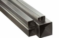
GOST Cast iron pipes contains the necessary requirements, subject to which it is possible to manufacture high-quality elements for the construction of pipelines. To ensure their protection against corrosion, oil bitumen coating is used on the outside and inside. As a result of processing, the inner surface of the cast-iron pipe becomes smooth. The requirements for such products depend on the casting method and are described in our article.
Requirements for cast iron pipes
Pipes made by casting using molds
Water pipes made by casting using sand molds must, in accordance with GOST 5525-88 (instead of 5525-61), meet the following requirements:
- The length of the pipe should be in the range from 2 to 6 m. At the same time, the size of the nominal diameter in it (D y) is in the range from 65 mm to 1200 mm. (It can be compared - cast iron pipes 9583 75 must correspond to D y, equal to from 65 to 1000 mm, and a length of 2-10 m. Only a socket connection is provided for such pipes).

- The pipe can be flanged or socketed.
- Pipes are made using casting (centrifugal, as well as semi-continuous).
- The wall of the water pipe must be at least 6.7 mm thick (maximum value - 31 mm). According to this parameter, 3 classes of cast-iron pipes for water pressure systems are distinguished: A, B, LA.
- In accordance with GOST, cast iron pressure pipes are calculated for operation under conditions of both normal pressure (1 MPa) and increased pressure (up to 1.6 MPa). When testing pipes for tightness, a pressure is created corresponding to a value of at least 2.5, maximum - 4 MPa (the pressure level during testing depends on D for the pipe and its class).

Hydraulic testing is carried out before applying the bituminous coating. Suitable pipes are recognized, which during the tests were distinguished by the absence of leakage and sweating of the walls.
- In the manufacture of connecting parts to water pipes, gray cast iron or chill molds are used.
As an example of marking - CHNR 400AX6000 - cast-iron water pipes GOST 5525-61 can be considered:
- in the CNR marking it means “cast iron pressure socket pipe”;
- 400 is the size of the diameter of the conditional passage in the pipe,
- A is a marking indicating the class to which the pipe supply class corresponds,
- 6000 - the size of the pipe length in millimeters.
Pipes made by centrifugal casting
Cast iron sewer pipes manufactured by centrifugal casting from gray cast iron GOST 6942-98 (formerly 6942.0-69 and 6942-80), oblige to meet the following requirements:

- In accordance with this GOST, 2 classes of cast iron pipes are distinguished:
- class A (withstand a pressure of 0.1 MPa until an anti-corrosion bitumen coating is applied) Cast iron pipes for sewerage of GOST class A and the parts used to connect them are used in the construction of the most critical sections of the sewer network.
- class B (withstand a pressure of 0.1 MPa after applying a bituminous coating). Class B pipes are recommended for use in internal sewer systems in standard building construction.
- , made in accordance with GOST 6942.3-69 must have D y equal to 5 cm, 10 cm, 15 cm. At the same time, the length of the cast-iron pipe can vary, ranging from 50 cm to 210 cm, its wall thickness can be at least - 4 mm, maximum - 5.5 mm, possibly an average value of 4.5 mm.

Cast iron pipe GOST 6942 98 is intended for the construction of internal sewer systems in buildings (D y is from 50 mm to 1200 mm, the pipe size is 2 to 6 m long).
An example of marking a pipe made of cast iron according to GOST 6942 - "TCHK-50-1500-B" stands for:
- PTCHK means "cast iron pipe for sewerage",
- 50 is D y in millimeters,
- B is the delivery class.
The quality of cast iron pipes
Pipe Certificate
When supplying pipes made of cast iron, as well as for their connection, a certificate must be attached, which indicates:
- manufacturer (official name),
- customer (official name),
- batch number and standard number,
- name of the product, its dimensions (in the case of pipes - footage, weight, quantity),
- test pressure and data obtained during mechanical testing.

Scope of application
The use of pipes made of cast iron
Scopes of cast-iron pipes:
- construction of sewer systems;
- construction of pressure pipelines;
- construction of heat supply systems;
- during the installation of oil pipelines;
- in fire water supply systems;
- when creating pipelines for the chemical and mining industries.
The vastness of the scope is caused by a long list of product advantages. Consider the advantages of cast iron pipes compared to plastic counterparts:
- higher strength;
- increased wear resistance;
- lower noise level;
- increased fire safety;
- increased stability when changing temperature indicators;
- lower susceptibility to stretch.
Quality control of cast iron pipes

Verification includes the following steps:

- The length of the socket of the sewer pipe should be in the range from 60 to 80 mm.
- The length of the cast-iron sewer pipe must be at least 2 m, but not more than 7 m, while the wall thickness is from 10 to 12 mm.
- The diameter of a pipe made of cast iron varies according to the brand of pipes:
- brand ChG - from 50 to 150 mm,
- VChShG brand - up to 500 mm.
- At a break, the pipe should be characterized by uniformity, fine grain and uniformity.
- Inspection is carried out visually and by tapping to detect cracks and hidden defects.
- Pipes pig-iron pressure head bell-shaped GOST obliges to correspond to especially high requirements. The normal width of the gap at the joint with a pipe diameter starting from 50 mm (maximum - 100 mm) is considered to be a distance of 5-6 mm.
Despite the widespread use of pipes made of new materials for the construction of pipelines of various types, the relevance of using cast iron pipes remains very high today.
Intra-house sewerage is a component of a comfortable human life. It is arranged from a set of materials, in particular from pipes and fittings made of cast iron.

Cast iron sewer pipes
This standard is an official document. According to its requirements should be made:
- cast iron sewer pipe GOST 6942 98 in three sizes;
- shaped parts to it, providing the device of internal sewerage.
Application area
GOST requirements are mandatory for cast iron sewer pipes and fittings used for internal sewerage systems.
Normative references
The standard was developed taking into account a dozen other existing GOSTs. Among the main ones:
- 26358-84, which establishes general specifications for castings that are made from cast iron;
- 1412-85 for cast iron grades containing lamellar graphite;
- 26645-85 with tolerances for mass, dimensions, machining allowances for castings from alloys and metals;
- 9812-74, defining specifications for insulating petroleum bitumen;
- 11506-73, containing a method for determining the softening point of petroleum bitumen using a ball and ring;
- 15150-69, devoted to the peculiarities of the execution of technical products depending on climatic conditions.
Assortment
The standard set:
- assortment of cast-iron sewer pipes and fittings used in domestic sewerage;
- their graphic and alphabetic designation.
The list of fittings in the assortment includes:
- branch pipes, including compensatory, transitional ones;
- knees, including low ones;
- elbows 110°, 120°, 135° and 150°;
- taps-tees instrumental and transitional;
- indents;
- straight tees, including compensating, low, transitional, low transitional;
- oblique tees 45° and 60°;
- crosses:
- straight lines, including those with a displaced axis of withdrawal;
- oblique 45° and 60°;
- two-plane;
- couplings, including sliding ones;
- revisions;
- plugs;
- cleaning.
Construction types and dimensions
This section lists the designs and dimensions of all assortment items covered by the document. In particular, pipes are produced with an inner diameter of 50, 100 and 150 mm and different lengths. For the former, it is 750, 1000 and 2000 mm; the rest have two more sizes - 2100, 2200. In addition, a product with a diameter of 100 mm is produced with a length of 1250 mm.
For pipes, 4 types of sockets are installed. Shanks are provided to ensure a hermetic connection of the elements.
Shaped parts are made as follows:
- Branch pipes for pipes with nominal bore:
- 50 mm length 250, 350 and 400 mm.
- 100-200, 250 and 350.
- 150 — 400.
- Compensation pipes. Designed for pipes with an inner diameter of 100 and 150 mm. Their thickened part has a length of 130, 370 mm for the first and 130, 380 for the second. The narrowed part is the same for all - 80 mm.
- Branch pipes transitional for connection of pipes with a diameter of 100 and 50, 150 and 100 mm.
- Elbows (including low ones), bends, tee bends in right and left versions, offsets, tees (straight, straight transitional, low, compensating, oblique), crosses (straight, with offset axes of the branch, oblique, two-plane). Elements allow you to connect pipes of all diameters at an angle, with axes offset, at forks.
- Couplings (ordinary, sliding) for coaxial joining of pipes.
- Revisions, cleanings to monitor the condition, carrying out inside work during the operation of the sewer.
- Plugs for blocking exits.
Technical requirements
The standard states:
- The procedure for the manufacture of pipes and fittings, the mandatory availability of approved technological and design documentation.
- Requirements for product characteristics:
- The presence of bays, external slag layers, metal drops, growths is excluded.
- The maximum thickness of bleachings is allowed: 1 mm on the outer surfaces; 2 mm at the ends, on smooth sections 60 mm long.
- The maximum deviation (±2 mm) from the nominal inner diameters is set, ±9% of the length, 7.1 g/cm³ for the mass, 2 mm/r.m. for straightness.
- Requirements for materials, raw materials, components.
- Requirements for anti-corrosion coating of internal surfaces of products.
- The need for the manufacturer to supply complete products in accordance with customer requirements.
- Requirements for marking products with casting or indelible paint.
- Rules for placing pipes in cassette, bag, container packaging or in bundles. The main one is the alternating arrangement of the sockets in different directions.
Acceptance rules
Reception of fittings, pipes is carried out in batches, which are made in one shift and are issued according to quality indicators in one document. Verification by acceptance and periodic tests of products is carried out.
During the acceptance check:
- all products are subject to external inspection of the anti-corrosion coating; 2% of them are tested for stickiness;
- 0.5% of the batch are evaluated for compliance with the remaining requirements of GOST.
Periodic testing is carried out at least quarterly. Products that have passed the acceptance test are checked. At the same time, in 0.5% of products, the softening temperature of the anti-corrosion coating and the strength of its adhesion to metal are determined.
The section sets:
- Possibility of control check of production by the consumer on any noted sign.
- Rechecking the batch. It is carried out according to the indicator for which a deviation from the requirements of the standard is revealed. The scope of testing is doubled. If the batch is rejected, each product is accepted separately.
Control methods
According to GOST, methods for controlling manufactured products have been established. Mandatory verification is subject to:
- Depth of chill, dimensions of the bleached layer. It is determined by a ruler, a caliper on split products that were rejected according to other indicators.
- The quality and appearance of the surface of products, anti-corrosion coating on them. Do this by comparing visually with the standard.
- Compliance with the given sizes. The check is carried out in two mutually perpendicular planes using universal measuring instruments. The average of the measurements is considered the diameter of the products inside and out.
- Weight of products. It is determined by weighing on a balance having at least the second class of accuracy.
- Pipe straightness. It is carried out by placing the products on the control plate (on prismatic supports) and measuring the gap between them. The latter is determined by the height gauge.
- Product tightness. It is carried out by installing plugs with nozzles for the pump and pressure gauge at all inlets and outlets. The internal volume is filled with water at a pressure of 0.1 MPa and above, which is maintained for at least 15 seconds. Inspect products for water leakage, fogging of external surfaces. If present, the product will be rejected.
Transportation and storage
The standard allows transportation of products by any mode of transport. Be sure to comply with the rules of transportation that apply to it.
During storage, which is also provided for by state standards for external sewerage, pipes must be sorted according to nominal diameters, and fittings - according to standard sizes, assortment. Products are placed so as to protect them from possible mechanical damage.
Installation and operating instructions
Installation of products must be carried out in accordance with the current building codes and regulations (SNiP). At the same time, technologies are used that ensure the tightness of the connections, the performance of the sewage system.
The connection of elements can be performed by the method:
- caulking, in which the sockets are filled with heated sulfur or filled with tarred strand and cement;
- installation of a sealing cuff made of rubber.
manufacturer's warranty
The manufacturer guarantees that the products for domestic sewage produced by him comply with the requirements of this standard. At the same time, it establishes a warranty period for them:
- 3 years from date of manufacture for storage;
- 2 years from the start of operation of the facility where they are installed;
- 2 years from the date of sale, if the transaction was made during the warranty period of storage.
Certificate for cast iron sewer pipes
This type of product is not subject to mandatory certification. The manufacturer can obtain a certificate of conformity for it on a voluntary basis. The document has legal force and is a confirmation of:
- compliance of pipes, fittings with GOST 6942-98;
- their high quality, which is important for the status of the manufacturer in the eyes of customers.
The procedure for obtaining a certificate does not differ from the mandatory one. Includes testing of products in a special laboratory. Based on the protocol, a certified body (in Russia it is Rosstandart) issues a document.
GOST 6942-98
INTERSTATE STANDARD
PIPES CAST IRON SEWER
AND FITTINGS TO THEM
Specifications
INTERSTATE SCIENTIFIC AND TECHNICAL COMMISSION
ON STANDARDIZATION, TECHNICAL REGULATION
AND CERTIFICATIONS IN CONSTRUCTION
(MNTKS)
2 Normative references
This standard uses references to the following standards:
It is allowed, by agreement between the consumer and the manufacturer, to manufacture pipes without sockets and supply them complete with MF couplings. The length of such pipes may differ from those indicated in the table.
An example of a symbol for a cast-iron sewer pipeDy = 100 mm L = 2000 mm:
TChK-100-2000 GOST 6942-98

Table 4
In millimeters
|
Conditional pass Dy |
l min. |
|||||||||

An example of a branch symbol witha = 120° and Dy = 50 mm:
About 120°-50 GOST 6942-98
Same with a = 150° and Dat = 100D (extended) mm:
About 150°-100D GOST 6942-98

1 - socket type I, 2 - shank
Table 17
Dimensions in mm
|
Conditional pass |
Weight, kg |
||||
|
At a = 45° ± 1° 30" |
|||||
|
At a = 60° ± l° 30" |
|||||
4.20 Two-plane crosses
4.20.1 Two-plane crosses are manufactured in two versions: right and left.
4.20.2 The design and dimensions of two-plane crosses must correspond to those indicated on and in Table 18.
An example of a symbol for a two-plane crossDat = 150 mm in the right version:
KD-150 ´ 100 ´ 50 GOST 6942-98
The same, in the left version:
LKD-150 ´ 100 ´ 50 GOST 6942-98

a = 87° 30" ± 1° 30"; 1 - socket type I; 2 - socket type III; 3 - shank
Castings, the mass of which exceeds the maximum, are recognized as fit, provided that they comply with this standard in all other quality characteristics.
The anti-corrosion coating must be continuous, durable, smooth, free of cracks and bubbles, firmly bonded to the metal of the products and must not be sticky.
On the surface of the coating of pipes, ring marks from supports for rolling pipes are allowed, and on the surface of the coating of fittings - traces from the hooks of chain conveyor suspensions, as well as drips caused by the runoff of anti-corrosion composition from pipes and fittings, or coating discontinuities.
5.4 Completeness
5.4.1 The manufacturer must complete pipes and fittings for delivery in the range determined by the consumer's order.
5.5 Marking and packaging
Trademark of the manufacturer;
Symbol of the product;
Designation of this standard.
5.5.2 Pipes are packed in containers, bags, cassettes or bundles tied with wire.
When packing, the pipes are laid with sockets alternately in opposite directions. Shaped parts are placed on box pallets or containers in accordance with GOST 26598 - 6.3; , and applying the control methods specified in .
6.8. If during the check at least one product for any indicator does not meet the requirements of this standard, then a second check is carried out for this indicator of twice the number of products from that batch.
If the re-test results are unsatisfactory, the batch of products is rejected or piece-by-piece acceptance of the products is carried out with a check of the indicators for which unsatisfactory results were obtained during the re-test.
7 Control methods
7.1 Chill depth and dimensions of the bleached layer () are checked on products rejected for other indicators by splitting them and measuring the depth and dimensions of the bleached layer with a ruler or caliper according to GOST 166.
7.2 The appearance and quality of the surfaces of products () and the appearance of the anti-corrosion coating of products () are checked visually without the use of magnifying instruments by comparing the product under test with the standard.
7.3 Deviations from the dimensions of pipes and fittings (-) are checked with universal measuring instruments that provide the necessary measurement accuracy. Measurements are carried out in two mutually perpendicular directions. The arithmetic mean of the results of two measurements is considered the outer (inner) diameter. In this case, the result of each measurement must be within the tolerance limits.
7.4 Checking the mass of products and deviations from it () is carried out by weighing products on a balance with an accuracy class not coarser than the 2nd.
7.5 Determining the presence and value of pipe non-straightness ()
7.5.1 Fixtures and tools:
Control horizontal plate;
Two steel prismatic supports of the same height.
7.5.2 Carrying out the test
Two prismatic supports are installed on the control plate parallel to each other at a distance from each other more than half the length of the tested pipe, and the pipe is laid on them with a deflection down. With the help of a height gauge, with an accuracy of 0.1 mm, measure the distance from the surface of the plate to the lowest point of the pipe at the place of its greatest deflection.
7.5.3 Scoring test results
The value of the deviation from the straightness of the pipe per 1 m of its lengthDcalculated according to the formula
where a is the height of the support, mm;
b - distance from the horizontal surface of the plate to the bottom of the pipe, mm;
l - distance between prismatic supports, m.
7.6 The softening temperature of the anti-corrosion coating () is checked according to GOST 11506.
7.7 The adhesion strength of the anti-corrosion coating to the metal of the product () is checked by applying cuts in the form of a grid to the coating with a knife blade with distances between the cut lines of at least 40 mm.
The adhesion of the coating is considered strong if the coating does not peel off during incisions.
7.8 The stickiness of the anti-corrosion coating () is checked at an ambient temperature of 15 to 30 ° C by lightly pressing a clean sheet of writing paper to the product coating in accordance with GOST 18510.
The coating is considered non-tacky if no traces of the coating remain on the paper after removal.
The stickiness of the coating is checked no earlier than 24 hours after its application to the product.
7.9 Checking the tightness of pipes and fittings ( )
7.9.1 Fixtures, materials and equipment:
Stand equipped with a pressure gauge with a division value not coarser than 0.01 MPa (0.1 kgf / cm 2);
A pump that creates a hydraulic pressure of 0.2 MPa (2 kgf / cm 2);
Plugs (deaf and with nozzles).
7.9.2 Carrying out the test
The assembled pipes and fittings are placed on the stand, and a plug with a pipe for connecting to the pump is installed on the hole closest to the pump, and a plug with a pipe for draining water is installed on the other hole. If there are other holes, then blind plugs are installed on them. Using a pump, the tested section of the pipeline is filled with water, the pipe for draining water is closed with a valve or other locking device and a pressure of at least 0.1 MPa (1.0 kgf / cm 2) is created in it. This pressure is maintained for at least 15 s, during which the joints of the pipeline section are inspected.
7.9.3 Test results
A section of the pipeline is considered sealed if, during its inspection, no water leaks through its walls or socket joints, fogging of the outer surfaces of pipes and fittings is detected.
8 Transport and storage
8.1 Pipes and fittings are transported by all means of transport in accordance with the rules for the carriage of goods in force for this type of transport.
8.2 Pipes should be stored sorted by nominal diameters, fittings - by types and standard sizes in conditions that exclude the possibility of mechanical damage to products.
9 Installation and operating instructions
9.1 Installation of pipes and fittings must be carried out according to the technology that ensures their operability and tightness of connections, in accordance with building codes and regulations.
9.2 Pipes and fittings can be connected to each other by caulking the sockets with a tarred strand and cement or by pouring heated sulfur, as well as using a rubber sealing cuff.
10 Manufacturer's warranties
10.1 The manufacturer guarantees the conformity of pipes and fittings to them with the requirements of this standard, subject to the rules of transportation, storage, installation and operation.
10.2 Warranty period of storage - 3 years from the date of manufacture.
Warranty period of operation - 2 years from the date of putting the object into operation or sale within the warranty period of storage.
Keywords:cast-iron sewer pipes, fittings, internal sewerage system of buildings
GOST 6942-98
INTERSTATE STANDARD
Specifications
Official edition
INTERSTATE SCIENTIFIC AND TECHNICAL COMMISSION FOR STANDARDIZATION, TECHNICAL REGULATION AND CERTIFICATION IN CONSTRUCTION (ISTC)
Foreword
1 DEVELOPED by the Research Institute of Sanitary Engineering (Scientific Research Institute of Sanitary Engineering) of the Russian Federation
INTRODUCED by Gosstroy of Russia
2 ADOPTED by the Interstate Scientific and Technical Commission for Standardization, Technical Regulation and Certification in Construction (ISTCS) on November 12, 1998
|
State name |
Name of the public administration body for construction |
|
Republic of Armenia |
Ministry of Urban Development of the Republic of Armenia |
|
The Republic of Kazakhstan |
Committee on Housing and Construction Policy under the Ministry of Energy, Industry and Trade of the Republic of Kazakhstan |
|
Republic of Kyrgyzstan |
State Inspectorate for Architecture and Construction under the Government of the Kyrgyz Republic |
|
The Republic of Moldova |
Ministry of Territorial Development, Construction and Public Utilities of the Republic of Moldova |
|
the Russian Federation |
Gosstroy of Russia |
|
The Republic of Tajikistan |
Gosstroy of the Republic of Tajikistan |
3 INSTEAD OF GOST 6942.0-80 - GOST 6942.24-80, GOST 4.227-83.
4 ENTERED INTO EFFECT on January 1, 1999 as the state standard of the Russian Federation by the Decree of the Gosstroy of Russia dated December 31, 1998 No. 31.
This standard cannot be fully or partially reproduced, replicated and distributed as an official publication on the territory of the Russian Federation without the permission of the Gosstroy of Russia
ISBN 5-88111-166-4 © Gosstroy of Russia, GUP TsPP, 1999
1 area of use............................................... ....................................one
3 Range.............................................. ................................................. ..2
4 Types, designs and dimensions .................................................. .......................6
5 Specifications .................................................................. ...............................36
6 Rules for acceptance ............................................... ...............................................38
7 Methods of control ............................................... ................................................39
8 Transport and storage............................................................... .................41
9 Instructions for installation and operation............................................... .........42
10 Manufacturer's Warranty............................................................... ...............................42
INTERSTATE STANDARD
PIPES CAST IRON SEWER AND SHAPED PARTS TO THEM
Specifications
CAST IRON WASTE PIPES AND FITTINGS Specifications
Introduction date 1999-01-01
1 area of use
This standard applies to cast iron sewer pipes and fittings for them intended for internal sewerage systems of buildings.
Mandatory requirements for product quality are set out in: 5.1; 5.2.2 - 5.2.4; 5.2.7; 5.2.8; 5.3.1; 5.3.2.
2 Normative references
GOST 164-90 Height gauges. Specifications
GOST 166-89 Calipers. Specifications
GOST 1412-85 Cast iron with lamellar graphite for castings. Stamps
GOST 9812-74 Oil insulating bitumen. Specifications
GOST 11506-73 Petroleum bitumen. Ring and ball softening point method
GOST 15150-69 Machinery, instruments and other technical products. Versions for different climatic regions. Categories, conditions of operation, storage and transportation in terms of the impact of environmental climatic factors
Official edition
GOST 18510-87 Writing paper. Specifications GOST 26358-84 Cast iron castings. General specifications GOST 26598-85 Containers and packaging equipment in construction. General specifications
GOST 26645-85 Castings from metals and alloys. Dimensional tolerances, weights and machining allowances.
3 Assortment
3.1 The assortment of pipes and fittings must correspond to that specified in Table 1.
Table 1
|
Name |
Nominal passages, mm |
Symbol |
||
|
graphic |
literal |
|||
|
Branch pipes | ||||
|
Branch pipes compensatory | ||||
|
Adapter pipes | ||||
|
Name |
Nominal passages, mm |
Symbol |
||
|
graphic |
literal |
|||
|
Knees low | ||||
|
Elbows 110° and 120° |
About 110°"/> y or |
|||
|
Elbows 135° | ||||
|
Elbows 150° | ||||
|
Elbows-tees |
OTP-100x50 or |
|||
|
instrumental |
LOTPr-100x50 |
|||
|
Straight tees | ||||
Continuation of table I
|
Name |
Nominal passages, mm |
Symbol |
||
|
graphic |
literal |
|||
|
Equal expansion tees |
TPK-D y X d y |
|||
|
Straight low tees | ||||
|
Straight reducing tees |
TPR-100/50x100 |
|||
|
Straight reducing tees low |
TP PH-100/50x100 |
|||
|
45° and 60° oblique tees |
TK45°-D X d and TK6o°-i" y x d y |
|||
|
Crosses straight |
KP-£) y x d y |
|||
|
Crosspieces straight with offset axis of withdrawal |
KPS-D y X d y |
|||
|
Name |
Nominal passages, mm |
Symbol |
||
|
graphic |
literal |
|||
|
Crosses oblique 45° and 60° |
KK45°-D*d and KK60°-D y *d y |
|||
|
crosses two-plane |
cd-lxdxd lcd-g> y x<1 у х |
|||
|
Couplings | ||||
|
Stub | ||||
|
Elbows-tees transitional | ||||
|
Cleaning | ||||
4 Types, designs and dimensions
4.1 Pipes
4.1.1 The design and dimensions of the pipes must comply with those indicated in Figure 1 and Table 2.
It is allowed, by agreement between the consumer and the manufacturer, to manufacture pipes without sockets and supply them complete with MF couplings. The length of such pipes may differ from those indicated in the table.
An example of a symbol for a cast-iron sewer pipe D y \u003d 100 mm, L \u003d 2000 mm:
TChK-100-2000 GOST 6942-98
|
Conditional passage D y |
Construction length L | ||||||||||
|
Conditional passage D y |
Construction length L | ||||||||||
4.2 Sockets and shank fittings
4.2.1 Sockets of fittings are made of four types: I, II, III, IV.
4.2.2 The design and dimensions of sockets of type I must correspond to those indicated in Figure 2 and Table 3, type II - in Figure 3 and Table 4, type III - in Figure 4 and type IV - in Figure 5. Dimensions are given without taking into account the anti-corrosion coating . It is allowed to manufacture bells of types I, I, IV without an annular groove on the inner surface of the bells.

Table 3 In millimeters
|
Conditional passage D y | |||||||||||

* Dimensions for reference
Figure 3
Table 4 In millimeters

Figure 4

* Dimensions for reference
Figure 5
4.2.3 The design and dimensions of the shank of the fittings must comply with those indicated in the figure and table 5.

Table 5 In millimeters
4.3 Spigots
4.3.1 The design and dimensions of the branch pipes must comply with those indicated in Figure 7 and Table 6.
An example of a symbol for a branch pipe D y = 100 mm, L - 250 mm;
1 P-100-250 GOST 6942-98 2

1 - socket type I; 2 - shank Figure 7
Table 6 Dimensions in mm
4.4 Expansion pipes
4.4.1 The design and dimensions of the compensating nozzles must correspond to those indicated in Figure 8 and Table 7.
An example of a symbol for an expansion pipe D y = 100 mm:
PK-100 GOST 6942-98/2

Figure 8
Table 7 Dimensions in mm
4.5 Reducing pipes
4.5.1 The design and dimensions of the transition pipes must comply with those indicated in Figure 9 and Table 8.
An example of a symbol for a transition pipe D, = 50 mm and D y = 100 mm: y1
PP-50/100 GOST 6942-98 1 2

Figure 9
Table 8
4.6 Knees
4.6.1 The design and dimensions of the elbows must comply with those indicated in Figure 10 and Table 9.
An example of a symbol for an elbow D = 100 mm;
K-100 GOST 6942-98

a \u003d 92 ° 30 "± 1 ° 30"; J - socket type I; 2 - shank
Figure 10
Table 9 Dimensions in mm
4.7 Low knees
4.7.1 The design and dimensions of the low elbows must correspond to those shown in Figure 11. The mass of the low elbow is 3.4 kg. Conventional designation of the low knee:
KN-100 GOST 6942-98

1 - socket type IV; 2 - shank Figure 11
4.8 Elbows 110° and 120°
4.8.1 The design and dimensions of the bends must comply with those indicated in Figure 12 and in Tables 10 and 11.
An example of a symbol for a branch with a = 120° and D y = 50 mm:
About 120°-50 GOST 6942-98
The same, with a = 150° and D y = 100D (extended) mm:
About 150 ° - 100D GOST 6942-98

/ - socket type 1,2 - shank Figure 12
Table 10
Dimensions in mm
Table 11 Dimensions in mm
4.9 Instrument tees
4.9.1 Instrument bends-tees are made in two versions: right and left.
4.9.2 The design and dimensions of instrumental tee-bends must correspond to those indicated in Figure 13. The weight of the tee-bend is 7.0 kg.
Conventional designation of a branch-tee of instrumental in the right version:
OTPR GOST 6942-98 The same, in the left version:
LOTPr GOST 6942-98

I - socket type 1,2 - socket type III, 3 - shank
Figure 13
4.10 Indents
4.10L The design and dimensions of the indents must comply with those indicated in Figure 14 and Table 12.
An example of the indent symbol D y = 100 mm:
OTS-YuO GOST 6942-98

I - socket type I; 2 - shank
Figure 14
Table 12 Dimensions in mm
4.11.1 The design and dimensions of straight tees must comply with those indicated in Figure 15 and Table 13.
An example of a symbol for a straight tee D y \u003d 50 mm and d y \u003d 50 mm:
TP-50x50 GOST 6942-98 The same, long, Z) = 100 mm and d y = 100D mm:
TP-100x100D GOST 6942-98

Table 13 Dimensions in mm
|
Conditional pass |
Weight, kg |
||||
4.12 Straight expansion tees
4.12.1 The design and dimensions of direct expansion tees must correspond to those indicated in Figure 16 and Table 14.
An example of a symbol for a direct expansion tee D = 100 mm, d = 50 mm:
TPK-100x50 GOST 6942-98

1 - socket type II; 2 - socket type I; 3 - shank
Figure 16
Table 14
Dimensions in mm
4.13 Low straight tees
4.13.1 The design and dimensions of straight low tees must correspond to those shown in Figure 17. The weight of the tee is 5.8 kg.
Conventional designation of a straight low tee:
ТН- 100x100 GOST 6942-98

4.14.1 The design and dimensions of straight reducer tees must correspond to those shown in Figure 18. The weight of the tee is 6.8 kg.
Conventional designation of a straight reducing tee:
TPR-100/50x100 GOST 6942-98

Figure 18
4.15.1 The design and dimensions of straight transition low tees must correspond to those shown in Figure 19. The weight of the tee is 4.7 kg.
Symbol of a tee of direct transitional low: TPRN-100/50x100 GOST 6942-98

4.16 Oblique tees
4.16.1 The design and dimensions of oblique tees must comply with those indicated in Figure 20 and Table 15.
An example of a symbol for an oblique tee with a = 45°, D y = 100 mm and d y ~ 50 mm:
TK 45°-100x50 GOST 6942-98
The same, with 60°, D y = 150 mm and d = 100 mm:
TC 60°-150x100 GOST 6942-98

Table 15 Dimensions in mm
|
Conditional pass |
Weight, kg |
||||
4.17.1 The design and dimensions of straight crosses must correspond to those indicated in Figure 21 and Table 16.
An example of a symbol for a straight cross D \u003d 100 mm and d \u003d 50 mm:
U KP-100x50 GOST 6942-98

Figure 21
Table 16 Dimensions in mm
4.18.1 The design and dimensions of straight crosses with a displaced outlet axis must correspond to those shown in Figure 22. The weight of the tee is 7.6 kg.
Conventional designation of a straight cross with an offset axis of retraction:
KPS-100x50 GOST 6942-98

Figure 22
4.19 Crosses oblique
4.19.1 The design and dimensions of the oblique crosses must comply with those indicated in Figure 23 and Table 17.
An example of a symbol for an oblique cross with a = 45 °, D y = 100 mm and d y = 100 mm:
KK45°-100x100 GOST 6942-98
The same, with a \u003d 60 °, D y - 150 mm and d y \u003d 50 mm:
KK 60° -150x50 GOST 6942-98 1

Table 17 Dimensions in mm
|
Conditional pass | |||||
|
Weight, kg |
|||||
4.20 Two-plane crosses
4.20.1 Two-plane crosses are manufactured in two versions: right and left.
4.20.2 The design and dimensions of two-plane crosses shall correspond to those indicated in Figure 24 and Table 18.
An example of a symbol for a two-plane cross Z> y - 150 mm in the right version:
KD-150x100x50 GOST 6942-98
The same, in the left version:
L KD-150x100x50 GOST 6942-98


a \u003d 87 about 30 "± 1 ° 30"; 1 - socket type 1; 2 - socket type III; 3 - shank
Figure 24
Table 18 Dimensions in mm
4.21 Couplings
4.21.1 The design and dimensions of the couplings must comply with those indicated in Figure 25 and Table 19.
Coupling example Z) y = 100 mm:
MF-100 GOST 6942-98 7 1

Table 19
4.22 Sliding couplings
4.22.1 The design and dimensions of slip-on couplings shall comply with those indicated in Figure 26 and Table 20.
An example of a symbol for a sliding coupling D y \u003d 100 mm:
MfN-100 GOST 6942-98
! / / ;■ , 7-7-7


1 - socket type II Figure 26
Table 20 Dimensions in mm
4.23 Revision
4.23.1 The design and dimensions of the revisions should correspond to those indicated in Figure 27 and Table 21.
An example of a revision symbol Z> y =100 mm:
R-100 GOST 6942-98
4.23.2 It is allowed to place bolts in the A-A plane and make cover 2 from steel.


1 - socket type I; 2 - cover; 3 - gasket; 4 - body; 5 - shank; 6-
screw; 7 - bolt
Figure 27
Table 21
Dimensions in mm
4.24 Plugs
4.24.1 The design and dimensions of the plugs must comply with those indicated in Figure 28 and Table 22.
An example of a symbol for a plug D y \u003d 100 mm:
3-100 GOST 6942-98
4.24.2 It is allowed to place bolts in the B-B plane and make cover 3 from steel.


1 - bolt; 2 - nut; 3 - cover; 4 - gasket; 5 - body; 6 - shank
Table 22
Dimensions in mm
Branches-trosh
n transitional
4.25.1 The design and dimensions of transitional tee branches must correspond to those indicated in Figure 29. The mass of the transitional tee branch is 7.8 kg.
An example of a symbol for a transitional branch-tee:
OTP- 100x50 GOST 6942-98

1 - socket type I; 2 - shank Figure 29
4.26 Cleaning
4.26.1 The design and dimensions of the cleanings must comply with those indicated in Figure 30 and Table 23.
An example of a cleaning symbol:
Pr-100 GOST 6942-98
4.26.2 Cleanings must be supplied complete with all the parts shown in the figure and assembled.

1 - socket type I; 2 - nut; 3 - bolt; 4 - cover; 5 - gasket;
6 - body; 7 - shank
Figure 30
Table 23 Dimensions in mm
4.27 Dimensions and weight are given without anti-corrosion coating.
5 Technical requirements
5.1 Cast iron sewer pipes and fittings for them should be manufactured in accordance with the requirements of this standard, according to the design and technological documentation approved in the prescribed manner.
5.2 Characteristics
5.2.1 Pipes and fittings for them must not have defects that impair their installation and operational qualities: bays, build-ups, metal drops, slag deposits on the outer and inner surfaces. It is allowed to eliminate minor defects caused by the method of production and not deteriorating the quality of products.
5.2.2 Pipes and fittings for them should not have a chill over the entire outer surface with a depth of more than 1 mm, and on the ends and outer surface of the smooth ends of the pipes for a length of 60 mm from the end and at the places of separation of the molds on the fittings - with a depth of more than 2 mm.
5.2.3 Deviations from the nominal dimensions of the inner diameters of the sockets of pipes and fittings and the outer diameters of the smooth ends of pipes and shank fittings (before applying an anti-corrosion coating to the product) should not exceed ±2 mm. Deviations from the dimensions of construction lengths in products of all types and diameters should not exceed ± 0.9%.
5.2.4 It is allowed to thicken the walls of the smooth ends of the pipes by no more than 2 mm in a section up to 150 mm long and the shank of fittings in a section up to 70 mm long from their ends with a corresponding decrease in the internal diameters of the products in these places, as well as rounding from the outside ends of smooth ends of pipes and shank fittings.
5.2.5 Limit deviations from the nominal dimensions of castings of products, with the exception of those regulated in 3.2.3 and 3.2.4, must correspond to 11t accuracy class according to GOST 26645.
5.2.6 Deviations from the calculated values of the masses of products established in the design standards, and the dimensions of these products (when calculating which the density of cast iron is assumed to be 7.1 g / cm 3) must correspond to 11 t accuracy class according to GOST 26645.
Castings, the mass of which exceeds the maximum, are recognized as fit, provided that they comply with this standard in all other quality characteristics.
5.2.7 Deviations from the straightness of pipes D y 100 and D y 150 mm should not exceed 2 mm per 1 m of length, and pipes D y 50 mm - 5 mm per 1 m of length.
5.2.8 Pipes and fittings as an assembly after applying an anti-corrosion coating on their inner and outer surfaces and sealing the sockets must withstand a hydraulic pressure of at least 0.1 MPa (1.0 kgf / cm 2).
5.3 Requirements for raw materials, materials and components
5.3.1 Pipes and fittings for them must be made of gray cast iron with lamellar graphite in accordance with GOST 1412 and in accordance with the requirements for castings in accordance with GOST 26358.
5.3.2 The outer and inner surfaces of pipes and fittings must be coated with an anti-corrosion compound based on BNI 1U-3 bitumen in accordance with GOST 9812 or other compounds that provide a softening temperature of the anti-corrosion coating of at least 333 K (60 ° C) and operating conditions UHL 4 GOST 15150.
The anti-corrosion coating must be continuous, durable, smooth, free of cracks and bubbles, firmly bonded to the metal of the products and must not be sticky.
On the surface of the coating of pipes, ring marks from supports for rolling pipes are allowed, and on the surface of the coating of fittings - traces from the hooks of chain conveyor suspensions, as well as drips caused by the runoff of anti-corrosion composition from pipes and fittings, or coating discontinuities.
5.4 Completeness
5.4.1 The manufacturer must complete pipes and fittings for delivery in the range determined by the consumer's order.
5.5 Marking and packaging
5.5.1 Pipes and fittings must be marked, cast or applied with indelible paint on the end or face
flare surface of the bell or directly behind the bell and including:
Trademark of the manufacturer;
Symbol of the product;
Designation of this standard.
5.5.2 Pipes are packed in containers, bags, cassettes or bundles tied with wire.
When packing, the pipes are laid with sockets alternately in opposite directions. Shaped parts are placed on box pallets or containers in accordance with GOST 26598, while the load capacity of the container must be fully used.
6 Acceptance rules
6.1 Pipes and fittings are accepted in batches. The batch is considered the number of pipes and fittings manufactured during one shift and issued with one quality document.
6.2 To check the compliance of pipes and fittings with the requirements of this standard, the manufacturer conducts acceptance and periodic tests of products.
6.3 During acceptance tests, products are checked for compliance with the requirements:
5.2.2 - 0.5% of products from the batch;
5.2.1 and 5.3.2 in terms of the appearance of the anti-corrosion coating - 100% of the products in the batch;
5.2.3 - 5.2.8, 5.3.2 in terms of the stickiness of the anti-corrosion coating - at least 2% of the items from the batch.
6.4 Periodic tests are carried out at least once a quarter.
6.5 Products that have passed acceptance tests are subjected to periodic tests.
6.6 During periodic tests, products are checked for compliance with the requirements of 5.2.3; 5.5.1 and 5.3.2 in terms of determining the softening temperature of the anti-corrosion coating and its adhesion strength to metal in the amount of 0.5% of the products from the batch.
6.7 The consumer has the right to conduct a control check of pipes and fittings for any quality indicator, observing
the procedure for selecting products given in 6.3; 6.6 and applying the control methods specified in section 7.
6.8 If, during the check, at least one product for any indicator does not meet the requirements of this standard, then a second check is carried out for this indicator of twice the number of products from that batch.
If the re-test results are unsatisfactory, the batch of products is rejected or piece-by-piece acceptance of the products is carried out with a check of the indicators for which unsatisfactory results were obtained during the re-test.
7 Control methods
7.1 Chill depth and dimensions of the bleached layer (5.2.2) are checked on products rejected for other indicators by splitting them and measuring the depth and dimensions of the bleached layer with a ruler or caliper according to GOST 166.
7.2 The appearance and quality of the surfaces of products (5.2.1) and the appearance of the anti-corrosion coating of products (5.3.2) are checked visually without the use of magnifying instruments by comparing the product under test with the standard.
7.3 Deviations from the dimensions of pipes and fittings (5.2.3 - 5.2.5) are checked with universal measuring instruments that provide the necessary measurement accuracy. Measurements are carried out in two mutually perpendicular directions. The arithmetic mean of the results of two measurements is considered the outer (inner) diameter. In this case, the result of each measurement must be within the tolerance limits.
7.4 Checking the mass of products and deviations from it (5.2.6) is carried out by weighing products on a balance with an accuracy class of no coarser than 2.
7.5 Determining the presence and value of pipework (5.2.7)
and non-rectilinear
7.5.1 Fixtures and tools:
Height gauge according to GOST 164;
Control horizontal plate;
Two steel prismatic supports of the same height.
7.5.2 Carrying out the test
Two prismatic supports are installed on the control plate parallel to each other at a distance from each other more than half the length of the tested pipe, and the pipe is laid on them with a deflection down. With the help of a height gauge, with an accuracy of 0.1 mm, measure the distance from the surface of the plate to the lowest point of the pipe at the place of its greatest deflection.
7.5.3 Scoring test results
The value of the deviation from straightness of the pipe per 1 m of its length A is calculated by the formula
where a is the height of the support, mm;
b - distance from the horizontal surface of the plate to the bottom of the pipe, mm;
I - distance between prismatic supports, m.
7.6 The softening temperature of the anti-corrosion coating (5.3.2) is checked in accordance with GOST 11506.
7.7 The strength of adhesion of the anti-corrosion coating to the metal of the product (5.3.2) is checked by applying cuts in the form of a grid to the coating with a knife blade with distances between the cut lines of at least 40 mm.
The adhesion of the coating is considered strong if the coating does not peel off during incisions.
7.8 The stickiness of the anti-corrosion coating (5.3.2) is checked at an ambient temperature of 15 to 30 °C by lightly pressing a clean sheet of writing paper against the product coating in accordance with GOST 18510.
The coating is considered non-tacky if no traces of the coating remain on the paper after removal.
The stickiness of the coating is checked no earlier than 24 hours after its application to the product.
7.9 Checking the tightness of pipes and fittings (5.2.8)
7.9.1 Fixtures, materials and equipment:
Stand equipped with a pressure gauge with a division value not coarser than 0.01 MPa (0.1 kgf / cm 2);
A pump that creates a hydraulic pressure of 0.2 MPa (2 kgf / cm 2);
Plugs (deaf and with nozzles).
7.9.2 Carrying out the test
The assembled pipes and fittings are placed on the stand, and a plug with a pipe for connecting to the pump is installed on the hole closest to the pump, and a plug with a pipe for draining water is installed on the other hole. If there are other holes, then blind plugs are installed on them. Using a pump, the tested section of the pipeline is filled with water, the pipe for draining water is closed with a valve or other locking device and a pressure of at least 0.1 MPa (1.0 kgf / cm 2) is created in it. This pressure is maintained for at least 15 s, during which the joints of the pipeline section are inspected.
7.9.3 Test results
A section of the pipeline is considered sealed if, during its inspection, no water leaks through its walls or socket joints, fogging of the outer surfaces of pipes and fittings is detected.
8 Transport and storage
8.1 Pipes and fittings are transported by all means of transport in accordance with the rules for the carriage of goods in force for this type of transport.
8.2 Pipes should be stored sorted by nominal diameters, fittings - by types and standard sizes in conditions that exclude the possibility of mechanical damage to products.
9 Installation and operating instructions
9.1 Installation of pipes and fittings must be carried out according to the technology that ensures their operability and tightness of connections, in accordance with building codes and regulations.
9.2 Pipes and fittings can be interconnected by caulking the sockets with a tarred strand and cement or by pouring heated sulfur, as well as using a rubber sealing cuff.
10 Manufacturer's warranties
10.1 The manufacturer guarantees the conformity of pipes and fittings to them with the requirements of this standard, subject to the rules of transportation, storage, installation and operation.
10.2 Warranty period of storage - 3 years from the date of manufacture.
Warranty period of operation - 2 years from the date of commissioning of the facility
operation or sale within the warranty period of storage.
UDC 696.133:669.13:006.354 OKS 91.140.70 Zh21 OKSTU 4925
Keywords: cast-iron sewer pipes, fittings, internal sewerage system of buildings
Interstate standard
PIPES CAST IRON SEWER AND SHAPED PARTS TO THEM
Specifications
GOST 6942-98
Head ed. otd. L, F. Zavidonskaya Editor L.N. Kuzmina Technical editor L.Ya. Head Corrector M.E. Shabalina, I.N. Gracheva Computer layout EL. Prokofiev