Plastic containers for water are an irreplaceable means for storing various substances. The Best Water Tanks in the Countryside - Which to Choose
General instructions
9.1. Capacities in water supply systems, depending on the purpose, should include regulating, fire, emergency and contact volumes of water.
9.2. Regulating water volume W p , m 3, in containers (reservoirs, tanks of water towers, counter-reservoirs, etc.) should be determined on the basis of water intake and withdrawal schedules, and in their absence, according to the formula
where Q days max - water consumption per day of maximum water consumption, m 3 / day;
TO n - the ratio of the maximum hourly supply of water to the regulating tank at water treatment stations, pumping stations or to the water supply network with a regulating tank to the average hourly flow per day of maximum water consumption;
TO h - coefficient of hourly irregularity of water withdrawal from a regulating tank or a water supply network with a regulating tank, defined as the ratio of the maximum hourly withdrawal to the average hourly consumption per day of maximum water consumption.
The maximum hourly water withdrawal directly for the needs of consumers who do not have regulating tanks should be taken equal to the maximum hourly water consumption. Maximum hourly withdrawal of water from the control tank by pumps for supply to water supply network if there is a regulating tank on the network, it is determined by the maximum hourly productivity of the pumping station.
In tanks at water treatment plants, an additional volume of water for washing filters, determined in accordance with clause 6.117, should be provided.
Note. When justified in containers, it is allowed to provide for the volume of water to regulate the daily irregularity of water consumption.
9.3. The fire volume of water should be provided in cases where obtaining the required amount of water for extinguishing a fire directly from a water supply source is technically impossible or economically inexpedient.
9.4. The fire volume of water in the tanks should be determined from the provision of:
fire extinguishing from external hydrants and internal fire hydrants in accordance with paragraphs. 2.12-2.17, 2.20, 2.22-2.24;
special fire extinguishing equipment (sprinklers, drenchers, etc., which do not have their own tanks) in accordance with paragraphs. 2.18 & 2.19;
maximum household, drinking and industrial needs for the entire period of fire extinguishing, taking into account the requirements of clause 2.21.
Note. When determining the fire volume of water in tanks, it is allowed to take into account its replenishment during extinguishing a fire, if water is supplied to them by water supply systems of I and II categories.
9.5. The fire volume of water in the tanks of water towers should be calculated for a ten-minute duration of extinguishing one external and one internal fire with the simultaneous highest water consumption for other needs.
Note. When justified, it is allowed to store the full fire volume of water in the tanks of the water towers, determined in clause 9.4.
9.6. When supplying water through one conduit in containers, it should be provided:
emergency volume of water, providing during the period of liquidation of the accident on the water main (clause 8.4) water consumption for household and drinking needs in the amount of 70% of the estimated average hourly water consumption and production needs according to the emergency schedule;
additional volume of water for fire extinguishing in the amount determined in accordance with clause 9.4.
Notes: 1. The time required to restore the emergency volume of water should be taken from 36 to 48 hours.
2. Restoration of the emergency volume of water should be envisaged by reducing water consumption or using reserve pumping units.
3. An additional volume of water for fire extinguishing is allowed not to be provided with the length of one water supply line no more than 500 m to settlements with a population of up to 5000 people, as well as to industrial and agricultural enterprises with a water consumption for external fire extinguishing not more than 40 l / s.
9.7. The volume of water in tanks in front of pumping stations for pumping or circulating water supply, operating evenly, should be taken on the basis of a 5-10-minute productivity of a pump of greater productivity.
9.8. The contact volume of water to ensure the required contact time of water with reagents should be determined in accordance with clause 6.167. The contact volume may be reduced by the amount of fire and emergency volumes, if any.
9.9. Tanks and their equipment must be protected from water freezing.
9.10. In containers for drinking water, the exchange of firefighter and emergency volumes of water must be ensured within a period of not more than 48 hours.
Note. When justifying the period of water exchange in containers, it is allowed to increase up to 3-4 days. In this case, it is necessary to provide for the installation circulation pumps, the performance of which should be determined from the condition of replacing water in containers within a period of not more than 48 hours, taking into account the flow of water from a water supply source.
9.11. The structures of tanks and water towers should be taken in accordance with clause 14.18.
Tank equipment
9.12. Water reservoirs and tanks of water towers should be equipped with: inlet and outlet pipelines or a combined inlet and outlet pipeline, overflow device, drain pipeline, ventilation device, brackets or ladders, manholes for the passage of people and transportation of equipment.
Depending on the purpose of the container, it should be additionally provided for:
devices for changing the water level, monitoring vacuum and pressure in accordance with clause 13.36;
skylights with a diameter of 300 mm (in non-potable water tanks);
flushing water supply (portable or stationary);
a device for preventing overflow of water from the tank (automation equipment or installation of a float shut-off valve on the supply pipeline);
device for cleaning the air entering the tank (in tanks for drinking water).
9.13. At the end of the supply pipeline in tanks and tanks of water towers, a diffuser with a horizontal edge or a chamber should be provided, the top of which should be located 50-100 mm above the maximum water level in the tank.
9.14. A confuser should be provided on the outlet pipeline in the tank; with a pipeline diameter of up to 200 mm, it is allowed to use a foot valve located in the pit (see clause 7.4).
The distance from the edge of the confuser to the bottom and walls of the container or pit should be determined from the calculation of the speed of water approaching the confuser no more than the speed of water movement in the inlet section.
The horizontal edge of the confuser, arranged in the bottom of the tank, as well as the top of the pit, must be 50 mm higher than the bottom edge.
A grate must be provided on the outlet pipeline or pit.
Outside the tank or water tower, on the outlet (inlet and outlet) pipeline, a device should be provided for taking water by tank trucks and fire engines.
9.15. The overflow device must be designed for a flow rate equal to the difference maximum feed and minimal water withdrawal. The water layer at the edge of the overflow device should be no more than 100 mm.
In reservoirs and water towers intended for drinking water, a hydraulic seal must be provided on the overflow device.
9.16. The discharge pipeline should be designed with a diameter of 100-150 mm, depending on the volume of the tank. The bottom of the tank must have a slope of at least 0.005 towards the drain pipeline.
9.17. Drain and overflow pipelines should be connected (without flooding their ends):
from non-potable water tanks - to a sewerage system for any purpose with a burst of a jet or to an open ditch;
from containers for drinking water - to a rainwater drain or to an open ditch with a break in the stream.
When connecting the overflow pipeline to an open ditch, it is necessary to provide for the installation at the end of the pipeline with a grid with gaps of 10 mm.
If it is impossible or inexpedient to discharge water through the drainage pipeline by gravity, a well should be provided for pumping out water with mobile pumps.
9.18. Air inlet and outlet when the position of the water level in the tank changes, as well as the exchange of air in tanks for storing fire and emergency volumes should be provided through ventilation devices that exclude the possibility of a vacuum exceeding 80 mm of water. Art.
In tanks, the air space above the maximum level to the bottom edge of the slab or the floor plane should be taken from 200 to 300 mm. Crossbars and slab supports can be flooded, and it is necessary to ensure air exchange between all sections of the coating.
9.19. Manhole hatches should be located near the ends of the supply, discharge and overflow pipelines. Manhole covers in drinking water tanks must have locking and sealing devices. The hatches of the tanks should rise above the insulation of the ceiling to a height of at least 0.2 m.
In drinking water tanks, all hatches must be completely sealed.
9.20. Pressure tanks and water towers for a fire extinguishing system high pressure should be equipped automatic devices ensuring their shutdown when starting fire pumps.
Reservoirs
9.21. The total number of tanks for one purpose in one unit must be at least two.
In all tanks in the node, the lowest and highest levels of fire, emergency and regulatory volumes should be respectively at the same elevations.
When one tank is turned off, the rest must store at least 50% of the fire and emergency water volumes.
The equipment of the tanks must provide the ability to independently turn on and empty each tank.
The device of one tank is allowed if there is no fire and emergency volumes in it.
9.22. The design of the valve chambers at the tanks should not be rigidly connected with the design of the tanks.
Water towers
9.23. Water towers can be designed with a tent around the tank or without a tent, depending on the operation mode of the tower, the volume of the tank, climatic conditions and the temperature of the water at the source of the water supply.
9.24. The barrel of the water tower may be used to accommodate industrial premises water supply systems that exclude the formation of dust, smoke and gas emissions.
9.25. In case of rigid termination of pipes in the bottom of the tank of the water tower, expansion joints should be provided on the risers of the pipelines.
9.26. A water tower that is not included in the lightning protection zone of other structures must be equipped with its own lightning protection.
Fire tanks and reservoirs
9.27. The storage of the fire volume of water in special tanks or open reservoirs is allowed for enterprises and settlements specified in the note. 1 to item 2.11.
9.28. The volume of fire tanks and reservoirs should be determined based on the estimated water consumption and the duration of extinguishing fires in accordance with paragraphs. 2.13-2.17 and 2.24.
Notes: 1. The volume of open water bodies must be calculated taking into account the possible evaporation of water and the formation of ice. Exceeding the edge of an open reservoir over the highest level water in it must be at least 0.5 m.
2. To fire tanks, reservoirs and receiving wells, free access of fire trucks with road surface must be provided in accordance with clause 14.6.
3. At the locations of fire tanks and reservoirs, signs should be provided in accordance with GOST 12.4.009-83.
9.29. The number of fire tanks or reservoirs must be at least two, while each of them must store 50% of the volume of fire extinguishing water.
The distance between fire tanks or reservoirs should be taken in accordance with clause 9.30, while the water supply to any point of the fire should be provided from two adjacent reservoirs or reservoirs.
9.30. Fire tanks or reservoirs should be placed from the conditions of their service to buildings located within the radius:
in the presence of auto pumps - 200 m;
in the presence of motor pumps - 100-150 m, depending on the type of motor pumps.
To increase the radius of service, it is allowed to lay dead-end pipelines from reservoirs or reservoirs with a length of no more than 200 m, taking into account the requirements of clause 9.32.
The distance from the point of water intake from reservoirs or reservoirs to buildings of III, IV and V degrees of fire resistance and to open warehouses of combustible materials must be at least 30 m, to buildings of I and II degrees of fire resistance - at least 10 m.
9.31. The supply of water for filling fire tanks and reservoirs should be provided through fire hoses up to 250 m long, and in agreement with the State Fire Supervision authorities - up to 500 m long.
(Modified edition, Amendment No. 1)
9.32. If the direct intake of water from a fire tank or reservoir by auto pumps or motor pumps is difficult, it is necessary to provide receiving wells with a volume of 3-5 m 3. The diameter of the pipeline connecting the reservoir or reservoir with the receiving well should be taken from the condition of passing the estimated water consumption for external fire extinguishing, but not less than 200 mm. In front of the receiving well, on the connecting pipeline, a well with a valve should be installed, the steering wheel of which must be brought out under the hatch cover.
On the connecting pipeline from the side of the reservoir, a lattice should be provided.
9.33. It is not required to equip fire tanks and reservoirs with overflow and drain pipelines.
10. SANITARY PROTECTION ZONES
General instructions
10.1. Sanitary protection zones 1 should be provided for all designed and reconstructed water pipelines for household and drinking purposes in order to ensure their sanitary and epidemiological reliability.
1 Hereinafter referred to as “zone”.
10.2. Water supply zones should include a water supply source zone at the point of water intake (including water intake facilities), a zone and a sanitary protection strip of 2 water supply facilities ( pumping stations, water treatment stations, tanks) and the sanitary protection strip of water pipelines
2 Further - "band".
The zone of the water supply source at the point of water intake should consist of three zones: the first - strict regime, the second and third - restriction regimes. The zone of water supply facilities should consist of the first belt and a strip (when the water supply facilities are located outside the second belt of the zone of the water supply source).
10.3. The design of the sanitary protection zones of the water supply system should be developed using the data of the sanitary-topographic survey of the territories planned for inclusion in the zones and strips, as well as the corresponding hydrological, hydrogeological, engineering-geological and topographic materials.
10.4. The project of the sanitary protection zones of the water supply system should determine: the boundaries of the zones of the water supply source, zones and strips of water supply facilities and the strip of water conduits, a list of engineering measures for the organization of zones (construction objects, demolition of buildings, landscaping, etc.) and a description of the sanitary regime in the zones and stripes.
10.5. The design of the sanitary protection zones of the water supply system must be coordinated with the authorities of the sanitary-epidemiological service, geology (when using groundwater), as well as with other interested ministries and departments and be approved in the prescribed manner.
10.6. Engineering activities to eliminate pollution of territories, watercourses, reservoirs and aquifers in the second and third belts of zones, as well as within the belts, should be carried out at the expense of enterprises that are sources of these pollution.
10.7. The design of the water supply zones should be developed taking into account the development of the water supply system for the future.
BOUNDARIES OF SANITARY PROTECTION ZONES
10.8. The boundaries of the first belt of the zone of a surface source of water supply, including the water supply canal, should be installed at distances from the water intake:
a) for watercourses (rivers, canals):
upstream - not less than 200 m;
downstream - not less than 100 m;
along the shore adjacent to the water intake - not less than 100 m from the water's edge during summer-autumn dry season;
in the direction to the opposite bank: if the width of the watercourse is less than 100 m - the entire water area and the opposite bank 50 m wide from the water's edge during the summer-autumn dry season and if the width of the watercourse is more than 100 m - a strip of water area with a width of at least 100 m;
at bucket-type water intakes, the entire water area of the bucket and the area around it with a strip of at least 100 m are included in the boundaries of the first belt;
b) for reservoirs (reservoir, lake):
in the water area in all directions - not less than 100 m;
along the shore adjacent to the water intake - at least 100 m from the water's edge at a normal retaining level in the reservoir and a summer-autumn dry season in the lake.
10.9. The boundaries of the second belt of the watercourse zone should be established:
upstream, including tributaries, based on the water flow rate averaged over the width and length of the watercourse or in its individual sections and the time of water flow from the belt boundary to the water intake at an average monthly water flow in the summer-autumn low-water period 95% of the availability of at least 5 days for IA, B, C, D, IIA of climatic regions and at least 3 days for other climatic regions;
downstream - not less than 250 m;
lateral boundaries - at a distance from the water's edge during summer-autumn dry season - with flat relief - 500 m, with mountainous terrain - up to the top of the first slope facing the watercourse, but not more than 750 m with a gentle slope and 1000 m with a steep slope ...
If there is a backwater or reverse flow in the river, the distance of the lower boundary of the second belt from the water intake should be established depending on hydrological and meteorological conditions, in agreement with the authorities of the sanitary and epidemiological service.
On navigable rivers and canals, the water area adjacent to the water intake within the fairway should be included within the boundaries of the second zone of the zone.
Note. In some cases, depending on local conditions, the lateral boundaries of the second belt may be increased in agreement with the authorities of the sanitary and epidemiological service.
10.10. The boundaries of the second belt of the reservoir zone, including tributaries, should be established from the water intake:
along the water area in all directions - at a distance of 3 km with the amount of winds up to 10% towards the water intake and 5 km with the amount of winds over 10%;
lateral boundaries - from the water's edge at a normal backwater level in the reservoir and summer-autumn dry season in the lake at a distance according to clause 10.9.
10.11. The boundaries of the third belt of the surface water supply zone should be upstream and downstream of the watercourse or in all directions along the water area of the reservoir the same as for the second belt; lateral boundaries - along the watershed, but not more than 3-5 km from the watercourse or reservoir.
Underground water sources
10.12. The boundaries of the first belt of the zone of an underground water supply source should be established from a single water intake (well, shaft well, capturing) or from the extreme water intake structures of a group water intake at distances:
30 m when using protected groundwater;
50 m when using insufficiently protected groundwater.
The boundaries of the first belt of the infiltration water intake zone should include the coastal area between the water intake and the surface water supply source, if the distance between them is less than 150 m.
For under-channel water intakes and a section of a surface source feeding an infiltration water intake or used for artificial replenishment of groundwater reserves, the boundaries of the first zone of the zone should be provided as for surface water supply sources in accordance with clause 10.8.
Notes: 1. For water intakes located on the territory of the facility, excluding the possibility of soil and groundwater contamination, as well as for water intakes located in favorable sanitary, topographic and hydrogeological conditions, the size of the first zone of the zone may be reduced in agreement with the local authorities of the sanitary and epidemiological service , but must be at least 15 and 25 m, respectively.
2. Protected groundwater includes waters of confined and non-confined aquifers that have a continuous impervious roof within all zones of the zone, which excludes the possibility of local recharge from the overlying insufficiently protected aquifers.
Insufficiently protected groundwater includes:
water of the first unconfined aquifer from the surface of the earth, which receives power in the area of its distribution;
waters of confined and non-confined aquifers, which, under natural conditions or as a result of the operation of the water intake, are fed in the area of the zone from the overlying insufficiently protected aquifers through hydrogeological windows or permeable rocks, roofs, as well as from streams and reservoirs by direct hydraulic connection.
10.13. In case of artificial replenishment of groundwater reserves, the boundaries of the first zone of the zone should be established from infiltration structures closed type(wells, mine wells) - 50 m, open type(pools, etc.) - 100 m.
10.14. The boundaries of the second belt of the underground water supply source zone are established by a calculation that takes into account the time of the microbial contamination of water to the water intake, taken depending on the climatic regions and the protection of groundwater from 100 to 400 days.
10.15. The boundary of the third belt of the zone of an underground water supply source is determined by a calculation that takes into account the time of the movement of chemical pollution of water to the water intake, which must be longer than the accepted duration of the water intake, but not less than 25 years.
10.16. With infiltration feeding of an aquifer, as well as with artificial replenishment of groundwater reserves from a surface source of the second and third belts of the zone of a surface source of water supply, it should be taken in accordance with paragraphs. 10.9-10.11.
Waterworks sites
10.17. The boundary of the first belt of the zone of water supply facilities must coincide with the fencing of the site of structures and be provided at a distance:
from the walls of filtered (drinking) water tanks, filters (except pressure), contact clarifiers with open surface water - not less than 30 m;
from the walls of other structures and the shafts of water towers - at least 15 m.
Notes: 1. By agreement with the authorities of the sanitary and epidemiological service, the first zone of the zone of free-standing water towers, as well as pumping stations operating without breaking the jet, may not be provided.
2. When water supply facilities are located on the territory of the enterprise, the indicated distances may be reduced in agreement with the local authorities of the sanitary and epidemiological service, but must be at least 10 m.
10.18. The sanitary protection strip around the first belt of the zone of water supply facilities located outside the second belt of the zone of the water supply source must have a width of at least 100 m.
Note. When the sites of water supply facilities are located on the territory of the object, the width of the strip may be reduced by agreement with the authorities of the sanitary and epidemiological service, but must be at least 30 m.
10.19. The sanitary protection zone from industrial and agricultural enterprises to the facilities of drinking water treatment stations should be adopted as for settlements, depending on the hazard class of production.
Water conduits
10.20. The width of the sanitary protection strip of water pipelines passing through undeveloped territory should be taken from the extreme water pipelines:
when laying in dry soils - at least 10 m with a diameter of up to 1000 mm and at least 20 m at large diameters; in wet soils - at least 50 m regardless of the diameter.
When laying water pipelines through a built-up area, the width of the strip, in agreement with the bodies of the sanitary and epidemiological service, may be reduced.
SANITATION MEASURES IN THE TERRITORY OF ZONES
Surface water supply
10.21. The territory of the first belt of the surface water supply source zone should be planned, fenced and landscaped, while the fence should be provided in accordance with clause 14.4.
10.22. The boundaries of the water area of the first zone of the zone are indicated by warning land signs and buoys. Above flooded water intakes located in the non-navigable part of the watercourse or reservoir, buoys with lighting should be installed; when located in the navigable part, the buoys are installed outside the waterway.
10.23. For the territory of the first zone of the zone, a sentry (alarm) alarm system should be provided.
10.24. On the territory of the first zone of the zone:
a) it is prohibited:
all types of construction, with the exception of the reconstruction or expansion of the main water supply facilities (ancillary buildings that are not directly related to the supply and treatment of water should be located outside the first zone of the zone);
accommodation of residential and public buildings, accommodation of people, including those working on the water supply;
laying of pipelines for various purposes, with the exception of pipelines serving waterworks;
release to surface sources Wastewater, bathing, watering and grazing, washing clothes, fishing, using pesticides and fertilizers for plants;
b) buildings must be sewerage with wastewater disposal to the nearest domestic or industrial sewage system or to local sewage treatment plant located outside the first zone of the zone, taking into account the sanitary regime in the second zone. In the absence of a sewerage system, waterproof cesspools should be arranged, located in places that exclude contamination of the territory of the first belt when removing sewage;
c) abduction must be ensured surface waters beyond the first belt;
d) only maintenance felling and sanitary felling are allowed.
10.25. On the territory of the second zone of the surface water supply source zone, it is necessary to:
a) to regulate the allocation of territories for settlements, medical and preventive and health-improving institutions, industrial and agricultural facilities, as well as possible changes in technology industrial enterprises associated with the increased risk of pollution of water supply sources with wastewater;
b) improve industrial, agricultural and other enterprises, settlements and separate buildings, provide for organized water supply, sewerage, the installation of waterproof cesspools, the organization of the disposal of contaminated surface wastewater, etc.;
c) accept the degree of purification of domestic, industrial and rainwater wastewater discharged into watercourses and reservoirs that meets the requirements of the "Fundamentals of water legislation of the USSR and the Union republics" and "Rules for the protection of surface waters from sewage pollution";
d) to carry out only thinning of the forest and sanitary felling of the forest.
10.26. In the second zone of the surface water supply source, it is prohibited:
a) pollution of territories with sewage, garbage, manure, industrial waste, etc .;
b) placement of warehouses for fuels and lubricants, pesticides and mineral fertilizers, accumulators, sludge storage facilities and other objects that can cause chemical pollution of water supply sources;
c) placement of cemeteries, cattle burial grounds, sewage disposal fields, filtration fields, agricultural irrigation fields, manure storages, silo trenches, livestock and poultry enterprises and other facilities that can cause microbial contamination of water supply sources;
d) the use of fertilizers and pesticides.
10.27. Within the second zone of the zone of surface water supply, in addition to the requirements of paragraphs. 10.25 and 10.26:
poultry breeding, washing clothes, swimming, tourism, water sports, beach construction and fishing in established places are allowed, subject to a special regime agreed with the sanitary-epidemiological service;
places of crossings, bridges and marinas should be established;
it is necessary, if there is navigation, to equip ships with special devices for collecting domestic water, sewage and solid waste, at the quays to provide drainage stations and receivers for collecting solid waste, and landing stages and guardhouses - to equip with receivers for collecting sewage;
it is prohibited to extract sand and gravel from a watercourse or reservoir, as well as dredging;
the location of pastures in the coastal strip at least 300 m wide is prohibited.
10.28. On the territory of the third zone of the zone of a surface source of water supply, the sanitary measures specified in clause 10.25 shall be envisaged.
10.29. In the forests located in the territory of the third zone of the zone, it is allowed to cut wood for main and intermediate use and assign standing timber to logging enterprises on a certain area (timber base), as well as long-term logging fund.
10.30. When using canals and reservoirs as sources of water supply, they should be periodically cleaned from sediments on the bottom and removed aquatic vegetation. Usage chemical methods the fight against overgrowing of canals and reservoirs is allowed subject to the use of drugs approved by the authorities of the sanitary and epidemiological service.
12.1 Reservoirs in water supply systems, depending on the purpose, should include regulating, fire, emergency and contact volumes of water.
12.2 The location of tanks on the territory of the water supply, their high-rise location in volumes should be determined during the development of the scheme and the water supply system based on the results of hydraulic and optimization calculations included in the system of structures and devices made in accordance with the requirements set out in 7.9 , as well as taking into account the provisions SP 8.13130.
As reservoirs, it is allowed to use underground, above-ground and above-ground reservoirs, tanks of water towers, as well as tanks located on the roofs of buildings, attics and intermediate technical floors.
Reservoirs (tanks), in which only the emergency stock is stored, are allowed to be located at the marks at which water from the reservoir can enter the network only when the normal free head in the network decreases to the emergency one. Such tanks or tanks must be equipped with overflow devices in case of failure of the check valve separating the tank (tank) from the network.
In the tank at water treatment plants, an additional volume of water for flushing the filters should be taken into account.
Note - When justified in the reservoir, it is allowed to provide for the volume of water to regulate not only hourly, but daily irregularity of water consumption.
12.3 When supplying water through one water conduit in the tanks, it should be provided:
emergency volume of water, providing during the time of liquidation of the accident on the water pipe ( 11.4 ) water consumption for household and drinking needs in the amount of 70% of the estimated average hourly water consumption and production needs according to the emergency schedule;
additional volume of water for fire extinguishing in the amount determined according to SP 8.13130.
Notes (edit)
1 The time required to restore the emergency volume of water should be taken from 36 to 48 hours.
2 Recovery of the emergency volume of water should be envisaged by reducing water consumption or using backup pumping units.
3 An additional volume of water for fire extinguishing is taken in accordance with SP 8.13130.
12.4 The volume of water in the tanks in front of the pumping stations of pumping, operating evenly, should be taken at the rate of 5 - 10-minute productivity of a pump of greater productivity.
12.5 The contact volume of water to ensure the required time of contact of water with reagents should be determined according to 9.127 ... The contact volume may be reduced by the amount of fire and emergency volumes, if any.
12.6 Tanks and their equipment should be protected from water freezing.
12.7 In reservoirs for drinking water, the exchange of firefighter and emergency volumes of water must be ensured within a period of not more than 48 hours.
Note - When justifying the period of water exchange in reservoirs, it is allowed to increase to 3 - 4 days. In this case, it is necessary to provide for the installation of circulation pumps, the performance of which should be determined from the condition of replacing water in tanks within a period of not more than 48 hours, taking into account the flow of water from a water supply source.
Tank equipment
12.8 Water reservoirs and tanks of water towers should be equipped with: supply and discharge pipelines or a combined supply and discharge pipeline, overflow device, drain pipeline, ventilation device, brackets or ladders, manholes for the passage of people and transportation of equipment.
Depending on the purpose, the tank should additionally include:
devices for measuring water level, control of vacuum and pressure;
skylights with a diameter of 300 mm (in non-potable water tanks);
flushing water supply (portable or stationary);
a device for preventing overflow of water from the tank (automation equipment or installation of a float shut-off valve on the supply pipeline);
device for cleaning the air entering the tank (in tanks for drinking water).
12.9 At the end of the supply pipeline in tanks and tanks of water towers, a diffuser with a horizontal edge or a chamber should be provided, the top of which should be located 50 - 100 mm above the maximum water level in the tank.
12.10 A confuser should be provided on the outlet pipeline in the tank; with a pipeline diameter of up to 200 mm, it is allowed to use a foot valve located in the pit (see. 10.5 ).
The distance from the edge of the confuser to the bottom and walls of the container or pit should be determined from the calculation of the speed of water approaching the confuser no more than the speed of water movement in the inlet section.
The horizontal edge of the confuser, arranged in the bottom of the tank, as well as the top of the pit, must be 50 mm higher than the bottom edge. A grate must be provided on the outlet pipeline or pit. Outside the tank or water tower, on the outlet (inlet and outlet) pipeline, a device should be provided for taking water by tank trucks and fire engines.
12.11 The overflow device should be designed for a flow rate equal to the difference between the maximum flow and minimum water withdrawal. The water layer at the edge of the overflow device should be no more than 100 mm.
In reservoirs and water towers intended for drinking water, a hydraulic seal must be provided on the overflow device.
12.12 The discharge pipeline should be designed with a diameter of 100 - 150 mm, depending on the volume of the tank. The bottom of the tank must have a slope of at least 0.005 towards the drain pipeline.
12.13 Drain and overflow pipelines should be connected (without flooding their ends):
from non-potable water reservoirs - to a sewerage system for any purpose with a bursting stream or to an open ditch;
from reservoirs for drinking water - to rainwater drainage or to an open ditch with a break in the stream.
When connecting the overflow pipeline to an open ditch, it is necessary to provide for the installation at the end of the pipeline with a grid with gaps of 10 mm.
If it is impossible or inexpedient to discharge water through the drainage pipeline by gravity, a well should be provided for pumping out water with mobile pumps.
12.14 The inlet and outlet of air when the position of the water level in the tank changes, as well as the exchange of air in tanks for storing fire and emergency volumes should be provided through ventilation devices that exclude the possibility of a vacuum exceeding 80 mm of water. Art.
In tanks, the air space above the maximum level to the bottom edge of the slab or the floor plane should be taken from 200 to 300 mm. Crossbars and slab supports can be flooded, and it is necessary to ensure air exchange between all sections of the coating.
12.15 Manholes should be located near the ends of the supply, discharge and overflow pipelines. Manhole covers in drinking water tanks must have locking and sealing devices. The hatches of the tanks should rise above the insulation of the ceiling to a height of at least 0.2 m.
In drinking water tanks, all hatches must be completely sealed.
12.16 The total number of tanks of one purpose in one unit must be at least two.
In all tanks in the node, the lowest and highest levels of fire, emergency and regulatory volumes should be respectively at the same elevations.
When one tank is turned off, the rest must store at least 50% of the fire and emergency water volumes.
The equipment of the tanks must provide the ability to independently turn on and empty each tank.
The device of one tank is allowed if there is no fire and emergency volumes in it.
12.17 The designs of the valve chambers at the tanks should not be rigidly connected with the design of the tanks.
12.18 Water towers may be designed with a tent around the tank or without a tent, depending on the tower operating mode, tank volume, climatic conditions and water temperature in the water supply source.
Note - Water level sensors used to control the operation of pumps supplying water to the tower should be heated in order to avoid overflow of water in winter.
12.19 The barrel of the water tower is allowed to be used to locate the production premises of the water supply system, excluding the formation of dust, smoke and gas emissions.
12.20 In the case of rigid termination of pipes in the bottom of the tank of the water tower, expansion joints should be provided on the risers of the pipelines.
12.21 A water tower that is not included in the lightning protection zone of other structures must be equipped with its own lightning protection.
12.22 The volume of fire tanks and reservoirs should be determined based on the estimated water consumption and the duration of extinguishing fires in accordance with SP 8.13130.
The wide scope of application of containers under water has become the reason for its distribution on the market. Water is used everywhere for industrial and domestic purposes, so it is necessary to select a container for water in accordance with the purposes of its operation. In the catalog of the company "AquaPoint" you will find many various designs, differing in modification, color and volume. Here you can find the best option for a favorable price.
Dependence of the shape of the water tank on the scope of application
If you need to buy a small volume plastic water container, you can choose round structures or cans. They allow you to carry fluid on long journeys. In other cases, it is necessary to take into account a number of factors affecting the choice of a product:
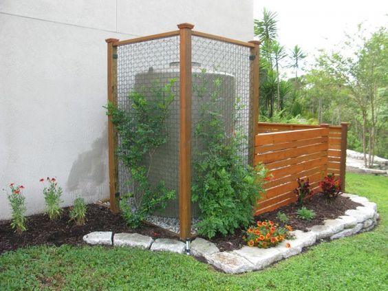
- Rectangular structures. Large parallelepiped tanks are easier to mount on supports. They are designed for fluid supply systems. They can be used to design outdoor showers or collect rainwater. It is convenient to use rectangular water tanks in summer cottages for collection, storage and watering.
- Round plastic water containers. It is more convenient to store large volumes of liquid in containers cylindrical... They are used to store and supply water to homes.
With the correct calculation of the use of the amount of liquid per person per day, you can select the optimal container volume. This will ensure optimal conditions operation of the product. We offer our customers several options that differ in shape and size.
Benefits of plastic water tanks
The AquaPoint company offers to buy a water tank with delivery all over Russia. All our products have quality certificates and are sold by favorable price... The main advantages of containers made on the basis of polyethylene are:
- variety of designs, shapes and sizes;
- light weight;
- simple and quick installation;
- corrosion protection;
- durability;
- environmental friendliness of the material;
- resistance to negative environmental conditions.
You can buy a container for water at the dacha and be sure of its harmlessness to the body. All products are made from environmentally friendly materials that do not react with liquids. We not only carry out the sale and delivery of goods, but are also ready to carry out the installation of packaging. Turning to the AquaPoint group of companies, you get high quality at a low price.
The company "KTR" LLC is engaged in the production, design and supply of various fire tanks for water storage. Here you can buy underground fire tanks, above ground of various capacities, shapes and sizes. All our products meet all the necessary requirements and SNiP.
The fire extinguishing system and storage tanks for the fire water supply are calculated in accordance with SNiP 2.04.01-85 Internal water supply and sewerage of buildings (clause 6 of the System fire-fighting water supply) and SNiP 2.04.02-84 Water supply external networks and structures (paragraphs 2.11-2.25).
Tanks for fire extinguishing are used in the absence of the possibility of fire extinguishing from a reservoir or a water supply source, if it is not economically viable.
It is recommended to use at least two fire tanks, and in case of failure of one of them, the second should contain at least 50% of the total volume of water.
Purpose of fire tanks
Water intake by fire engine in case of fire
- water supply pumping equipment for fire extinguishing system
- water storage
Advantages of fiberglass fire tanks
Anti-corrosion material - fiberglass reinforced plastic
- water intake system according to fire requirements
- ease of transportation and installation
Contents of delivery
The delivery set may include various equipment.
The most common manufacturing option is two parallel containers with a 315 intake pipe. In this case fire engine She takes it herself from the fire extinguishing container.
Installation of equipment
The reservoir for the fire water supply is mounted on a reinforced concrete slab. A sand preparation of 200 mm is made on the slab. The reservoir is lowered onto the slab and anchored to the embedded parts. The tank is backfilled with sand.
Technical characteristics of fire tanks
| Name | Volume, m3 | Diameter 1.0 m | Diameter 1.6 m | Diameter 2.0 m | Diameter 2.4 m | Diameter 3.0 m |
| Fire tank KTR-2 | 2 | 2,5 | ||||
| Fire tank KTR-3 | 3 | 3,8 | ||||
| Fire tank KTR-4 | 4 | 2,0 | ||||
| Fire tank KTR-5 | 5 | 2,5 | ||||
| Fire tank KTR-6 | 6 | 3,0 | ||||
| Fire tank KTR-7 | 7 | 3,5 | 2,2 | |||
| Fire tank KTR-8 | 8 | 4,0 | 2,5 | |||
| Fire tank KTR-9 | 9 | 4,5 | 2,9 | |||
| Fire tank KTR-10 | 10 | 5,0 | 3,2 | |||
| Fire tank KTR-12 | 12 | 3,8 | 2,7 | |||
| Fire tank KTR-15 | 15 | 4,8 | 3,3 | |||
| Fire tank KTR-20 | 20 | 6,4 | 4,4 | |||
| Fire tank KTR-25 | 25 | 8,0 | 5,5 | 3,5 | ||
| Fire tank KTR-30 | 30 | 9,6 | 6,6 | 4,2 | ||
| Fire tank KTR-40 | 40 | 8,8 | 5,7 | |||
| Fire tank KTR-50 | 50 | 11,1 | 7,1 | |||
| Fire tank KTR-55 | 55 | 12,2 | 7,8 | |||
| Fire tank KTR-60 | 60 | 8,5 | ||||
| Fire tank KTR-70 | 70 | 9,9 | ||||
| Fire tank KTR-80 | 80 | 11,1 | ||||
| Fire tank KTR-90 | 90 | 12,7 | ||||
| Fire tank KTR-100 | 100 | 14,2 |
Our company manufactures containers with a diameter of 600, 800, 1000, 1200, 1400, 1600, 1800, 2000, 2200, 2400, 2500, 3000, 3200, 3500, 4200 mm ..
Water tank in the country - photo ideas
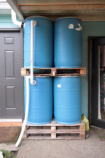
Let's not deny that water storage tanks are needed at any summer cottage. My husband and I are the first year of ownership summer cottage We suffered greatly from the fact that we had to carry water all the time in buckets from a water tower, which was 500 meters away from us. After a while, we got a suitable container for water in the country - a 250 liter blue plastic barrel.
Capacity for storing water in the country
Yes, it has greatly simplified and improved my life at the dacha - a water tank is consumed in three days, and we have water in the mains supply just every three days. So replenishment with fresh water occurs regularly.
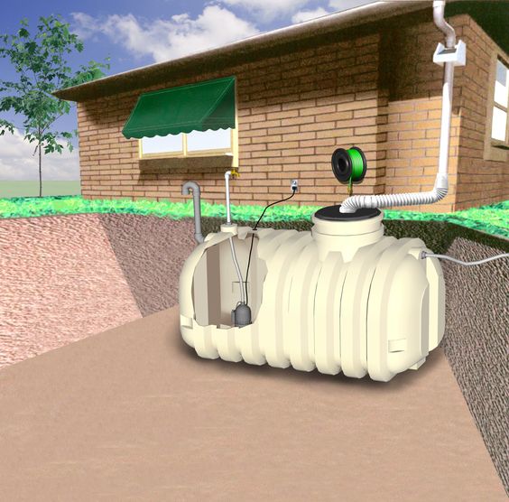
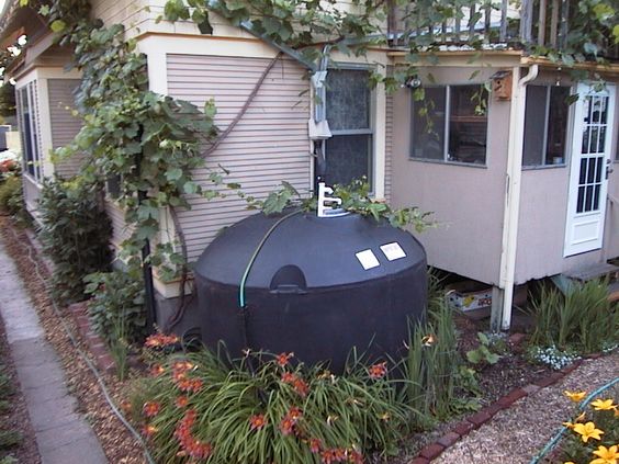
Such a capacity is especially relevant if there is no running water in the country house. In this case, you can think about a rainwater accumulator, at least you will have industrial water for irrigation. And you can collect sediments just in such containers.
Ideas for tanks for storing water in a summer cottage
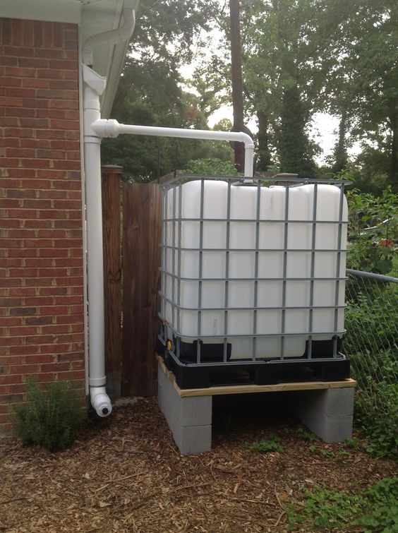
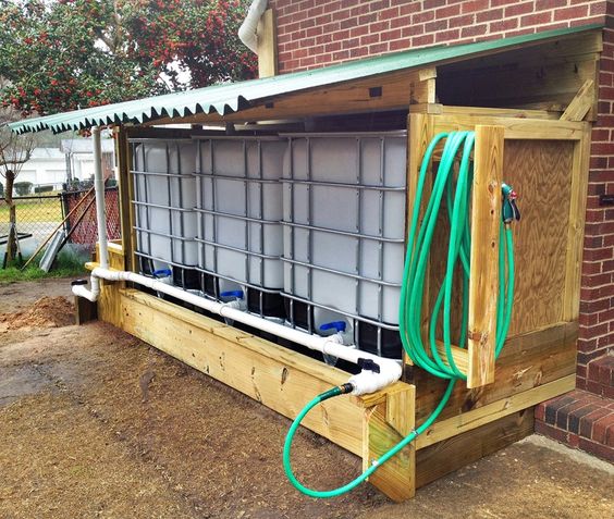
The most common water tanks are 100 l, 250 l, 500 l, 1000 l, 5000 l. Very convenient plastic container - reinforced eurocube metal frame... Calculate your own water consumption for each family member and purchase a slightly larger water tank, so to speak in reserve.
Plastic tanks for storing water in the country
Volumes of water tanks
If your consumption, like ours, is small, then you can purchase water tanks for the dacha in 100 l, 200 l, 1000 l. If the volumes are not enough, then you can combine several small containers into a single whole, while obtaining a significant increase in the total cubic capacity.
If your family and consumption are large, then immediately take water tanks of 2000 liters, 3000 liters or 5000 liters. Of course, you need to understand that large-volume containers are very expensive.
Capacity for storing water at a summer cottage
So, decide for yourself how much you need a container for storing water in the country?
Forms of water tanks
The most versatile are rectangular water tanks. They can be easily placed in a corner, joined together, stacked on top of one another. the same applies to rectangular containers- there is a wide variety of them on the market.
Such containers are often used for the accumulation and storage of drinking water, or industrial water for irrigation and shower.

Large capacity for collecting rainwater in the country
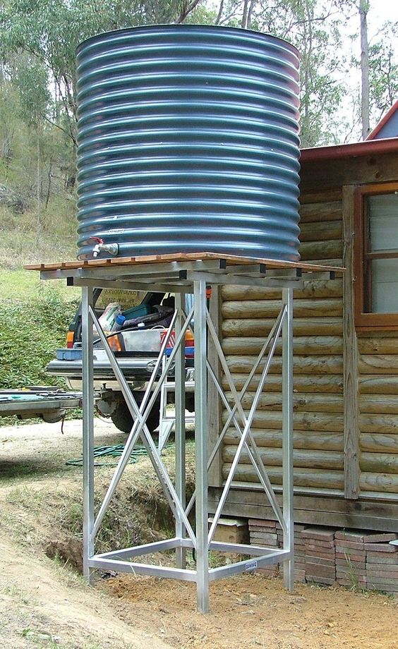
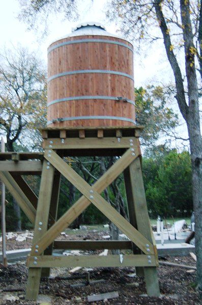
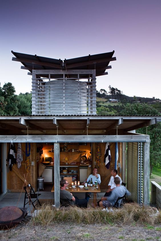
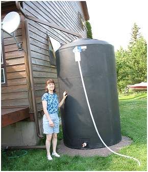
Round water tanks are also very popular - a similar tank for a summer residence can be installed on a pedestal and get the natural water pressure in your summer water supply. And still water tanks and reservoirs rectangular you can also climb to a podium - a tower and get a little pressure in the water supply system.
Drinking water tanks - which materials are suitable
When we were choosing what material our water tank would be for the cottage, we studied the reviews and opinions on the forums. In the end, we settled on plastic, simply placing the barrel in the shade, where the sun does not fall.
Large capacity for storing industrial water in the country
Stainless steel container
A very expensive container that meets all standards for food containers. Most often they are made in the form of barrels, tanks. Stainless steel is used specifically for drinking water, industrial water it makes no sense to keep in such an expensive container.
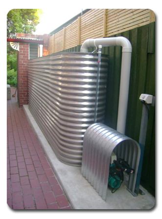
Stainless steel water tank
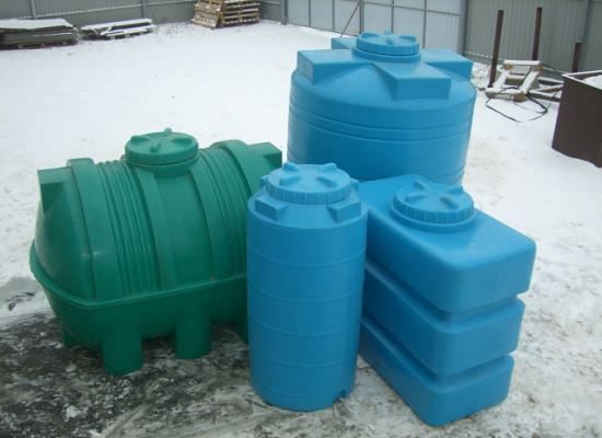
Plastic containers for water
Practical and inexpensive plastic water containers. It is easy to install, the container itself is quite light, without water, so install it on permanent place one adult can. You can store both drinking and industrial water, they come in completely different shapes in shape, you can easily find it for your needs.
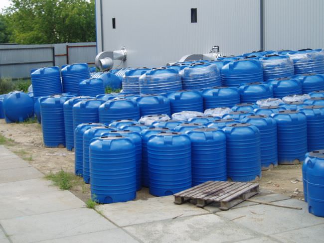
Plastic containers for water
I think that plastic containers under water - the most convenient and practical for the suburban area.
Metal containers for water
Most often, such containers are made from sheets of iron that are prone to corrosion, therefore, such tanks require processing. protective coating... This is exactly what allows such products to be cheap. In summer cottages, welded metal cubes are often found for storing water for irrigation.
Metal container for storing water in the country
Purpose of water storage tanks
According to their purpose, containers are divided into several categories. Next, we will consider each option in more detail.
Water storage capacity
There may be several such tanks on the site, we, for example, have a separate tank for irrigation, a tank for drinking, a barrel for collecting water from a well. Drinking water, as already said, is stored in a barrel, placed in the shade, where the sun does not get. For watering, the container is vice versa in the sun.
Rainwater tank
Capacity for storing and collecting rainwater in the country
In areas with an abundance of rain, it is advisable to install containers for collecting and storing rainwater. On the gutters from the roof rainwater collected in tanks and used later for irrigation or for some technical purposes. It rarely rains here and it makes no sense to install such a system.
Storage tank for water
Storage tanks for water in the country - photo ideas
Such containers can be placed in front of greenhouses, as my aunt does. As it is consumed, water is poured into such reservoirs. The material can be any, the aunt's simple metal barrels from under engine oil. Very convenient and budgetary - we got it as a gift from the mechanics from the enterprise where she works.
Tanks for storing water in the country for 3 cubic meters
Installing a water tank in the country
So, for storing water, you can use absolutely different products When buying containers for collecting water and storing it, think about how it will be installed. If you are alone, and there is no one to help you, then I recommend plastic.
Most often, either above-ground tanks or underground water tanks are installed, as well as, as already mentioned, raised on platforms - towers.
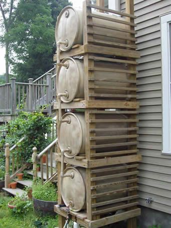
The idea of a container for storing water from plastic barrels
What you need to buy and install a tank under water
In most cases, the container is self-sufficient, and it already has a tap, a cover for filling water. Instead of a tap, pipes can be mounted to supply water through the water supply system directly to the house or for irrigation. You can connect a pump and compressor to get the pressure in the system.
Water tank for a summer residence - ideas
You can install the container on a tower and get an independent drain of water under low pressure. Some have tanks for storing water in heated attics, this allows you to use water in the country even during the off-season.
Large capacity for storing water in the country and in a country house
In my selection, I tried to find interesting photos ideas for your inspiration. See what options are there and choose for yourself for the future.
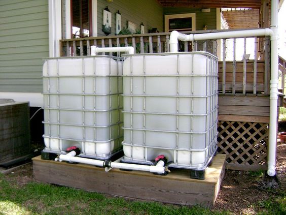
Eurocube - a container for water in the country
By purchasing, installing and filling a water container, you will provide yourself and your plants with liquid. You should not rely on the supply of water on a schedule, having made a reserve, you will not be able to rush to the dacha before the watering hours, but come without traffic jams at a convenient time. I wish you inspiration and creative success!


