Testing water networks for waterproof. Terms of Fire Water Supply
1. Basement of the event:
In fulfillment of the requirements of paragraph 55 of the Rules fire-fighting regime in Russian Federation (as amended by the Decree of the Government of the Russian Federation of 02/17/2014 No. 113) The head of the organization ensures the health of the sources of external fireproof water supply and organizes inspections of their performance at least 2 times a year (in spring and autumn) with the compilation of relevant acts.
2. Test Purpose:
Determine the possibility of obtaining compact jets with a height of at least 10 m with a full fire consumption of water and the location of the stems at the level the highest point The highest buildings of the object (4.4. SP 8.13130.2009 as editors 01.02.2011)
3. Terms of events:
Check fire hydrants to carry out the following conditions:
Starting water only at positive temperatures; At air temperature from 0 to -15 ° C, only an external inspection without starting water is allowed.
At temperatures below -15 ° C, the opening of the wells for inspection is prohibited in order to avoid loss of heat of the well itself.
4. Technical component of the activities:
4.1. When checking fire hydrants, it is necessary to reflect:
state of entrances to fire hydrants;
The placement of the hydrants in the wells should provide a free installation of the well cover and opening the hydrant cover and complete the foaming column;
the presence of pointers, the coordinate correspondence on the pointer to the actual location of the fire hydrant;
the presence and serviceability of the hatch and the well cover;
The integrity and health of the covers and threads of nipple, the upper square of the rod and the hydrant housing; the presence of a cover of hydrant riser;
the presence of water in the well, hydrant housing;
fastening the hydrant housing to the stand;
tightness of the valve, the ease of its opening and closing;
the state of the thread on the hydrant (by screwing the fire column);
Check the operation of the hydrant with the installation of the fire column and determine throughput (water flow) hydrant;
Specify the view and diameter of the water pipe on which the hydrant is installed.
4.2. Minimum distances internal surfaces Wells that must fit:
from pipe walls (with pipe diameter up to 400 mm) - 0.3 meters; (from 500 to 600 mm) - 0.5 meters, (more than 600 mm) - 0.7 meters;
from the plane of the flange (with the diameter of pipes up to 400 mm) - 0.3 meters, (more than 400 mm) - 0.5 meters;
From the edge of the terminal facing the wall (with pipe diameter up to 300 mm) - 0.4 meters, (300 mm) - 0.5 meters;
From the bottom of the pipe to the bottom (with the diameter of pipes up to 400 mm) - 0.25 meters, (from 500 to 600 mm) - 0.3 meters, more than 600 mm - 0.35 meters;
From the top of the valve rod with a sliding spindle - 0.3 meters; From the flywheel valve with not retractable spindle - 0.5 meters;
From the hydrant cover to the well cover not more than 450 mm vertically, and the distance to the light between the hydrant and the top of the shell is at least 100 mm;
The height of the working part of the wells should be at least 1.5 meters.
5. Water Tests:
5.1 Testing Method
This method of measuring water consumption from plumbing networks is to determine the time of filling specially broken tanks, as a rule, capacity is 500-1000 liters. At the same time, the calculation of water consumption is determined using the formula:
Q \u003d V / T (l / s)
where: V is the volume of the tank, l; t - tank fill time, p.
This method compared to others is the most accurate (the error does not exceed ± 1-2%).
5.2 Testing (measurement) with the help of a water meter
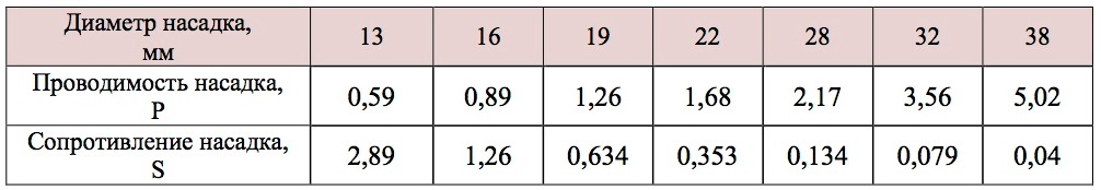
The barrel is additionally equipped with a pressure gauge and a set of replaceable nozzles of various diameters. The flow consumption of the trunk is determined by the formula of the expiration of the liquids from the nozzles:
Q. = √ H./ S. or Q. = P.· N -2., (l / s)
N - pressure in the plumbing network, M water.st.;
S - the resistance of the nozzle;
P is the conductivity of the fire trunk nozzle.
To determine the conductivity P and S, use the following data:
Table 1 Conductance of the Fire Station Nozzle
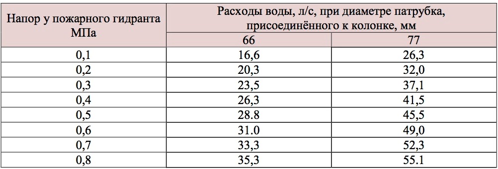
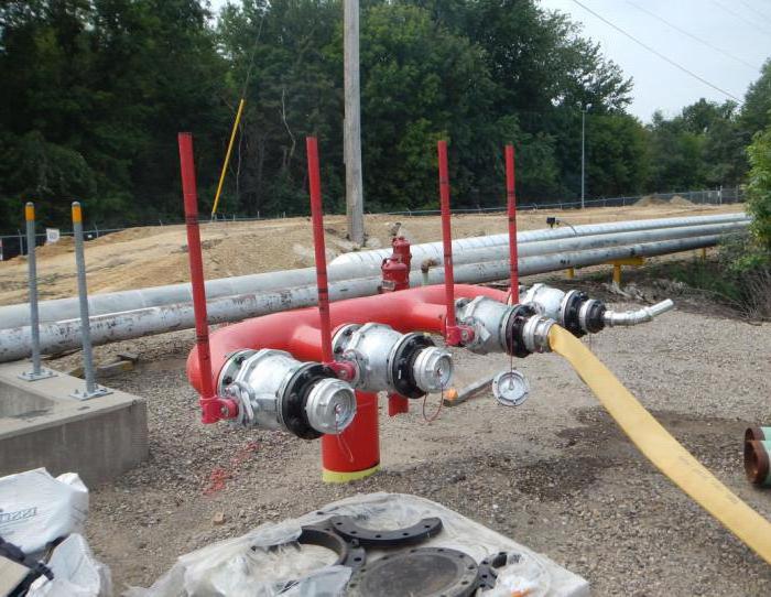
5.3. Test (measurement) using a fire column
When using this method, it is necessary to pre-trim the fire column, i.e. Determine water consumption depending on the testimony of the pressure gauge. The fire column is equipped with two cuts of pipes with a length of 500 mm, with a diameter of 66 mm (2.5) or 77 mm (3) with the connecting heads, a pressure gauge is installed on the column housing. The total consumption of water from the column installed on the fire hydrant is equal to the amount of costs through two nozzles. The total water reproduction of the network is determined by the total consumption of water from several columns mounted on fire hydrants of the test section of the water supply.
With a small waterproof of water networks, you can use one pipe of the column, and to connect the cap with the pressure gauge to another nozzle.
Water consumption through the fire column is determined by the formula:
Q. = P.· N -2., (l / s)
N - water pressure on the network, m;
P is the conductivity of the column.
Table 2 Waterproof Fire Columns
Number of open pipes column diameter nozzle average speaker conductivity
Table 3 Conducting a fire column
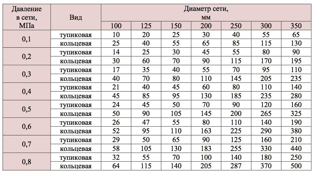
In areas of water supply networks with small diameters (100-125 mm) and a slight pressure (10-15 m), water fence is more advantageous to produce a suction line of the pump from the well, filling it with water from the hydrant to evil. In these cases, the consumption of water from the hydrant is somewhat greater than the consumption of water taken by the hydrant pump through the column.
Table 4 Waterproof Turning Network
Water production of the water supply network is determined using a fire column and a measuring instrument. Tests are carried out both under normal pressure and with the inclusion of risk pumps (pumping station).
For testing it is necessary:
Install the fire column on the hydrant;
Connect a smooth connector to the column;
Open the fire hydrant until full overlapping its drain canal;
measure free pressure;
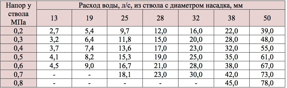
Compare the testimony of pressure gauges with tabular data, determine water production from the hydrant at the beginning of the water supply section, then repeat similar tests at the end of the water supply site. The average arithmetic value of the two values \u200b\u200bobtained during the test will be a water reproductive area of \u200b\u200bthe water supply network.
Water consumption through one nozzle of the fire column depending on its diameter and pressure at the hydrant.
6. List of characteristic faults of fire hydrants
Plate:
there is no fire hydrant pointer (coordination plate);
The data on the plate does not correspond to reality or poorly visible.
Well:
covered with soil, garbage, etc.; Asphalted;
It was forced by equipment, vehicles, etc.;
there is no entrance;
drowned;
not closed (flowing);
Low pressure on the network;
dropped;
there is no drainage of the well; shifted a set; no cover kit; no entry;
Finding does not allow to pronounce the opening.
Riser:
no riser;
Lowly located standing; shot down carving on riser; The riser is not fixed; The riser is clogged; crack in riser; no covering cover; shifted riser;
A drainage device does not work.
Stock :
no rod; rodbed rod; The rod is bent;
Long rod does not allow to make a start of water; large square stock; Straight strands.
Flange:
The bolts of the top flange prevent the column retroachment;
flow under the top or bottom flange; broken flange.
Highway:
disabled;
Not hermetic
No rubber ring.
7. Terms and definitions:
Water reproductive water supply - The amount of water supplied per unit of time, depending on the pressure in the network and the type of water supply network.
Water pipes high pressure
- Water pipe free pressure, in which it provides the height of a compact jet of the fire trunk at least 10 m at the level of the highest point of the highest building with full regulatory flow Water for fire extinguishing. SNiP 2.04.02.
Shut-off - 1) moving valve assembly, designed to overlap its passage section; 2) A device intended for feeding, adjusting and overlapping a fire extinguishing substance. GOST R 51052; NPB 83.
Sources of external fireproof water supply: External water supply networks with fire hydrants and water objectsused for fire extinguishing purposes. (3.1 SP 8.13130.2009 as amended, change. N 1 of 09.12.2010)
Manometer — 1) measuring device or measuring installation for measuring pressure or pressure difference; 2) the instrument for measuring pressures or pressure difference. GOST 8.271; STSEV 4840.
Test Methods - An organizational and methodological document, mandatory for implementation, including the test method, means and testing conditions, sampling, the algorithms for performing operations to determine the homogeneous or several interconnected characteristics of the object properties, the form of data presentation and the accuracy assessment, the accuracy of the results, safety requirements and security ambient. GOST 16504.
Head Fire Sleeve - Fire Sleeve for Transportation fire extinguishes under excess pressure. GOST 12.2.047.
Outer fireproof water supply (NPV) - The system of structures and devices delivering water through pipes from the water source to the consumption location. (p.3.5 SP 8.13130.2009 as amended, change. N 1 of 09.12.2010)
Fire column - Removable device installed on a fire hydrant for water take-off. GOST 12.2.047.
Firefish reservoir - Special reservoir or outdoor reservoir intended for storing fire volume water. SNIP 2.04.02.
Fire hydrot is a device for selecting water from a water supply network to extinguish a fire. GOST 12.2.047.
Fire Pump of Normal Davleni am single or multistage fire centrifugal pumpoperating at a pressure at an outlet to 1.5 MPa (15 kgf / cm2). NPB 163.
Fire stand - Detail of the pipeline for installing fire hydrant. GOST 12.2.047.
Maintenance - A complex of operations or operation to maintain health or health service when used for intended, storage and transportation. GOST 18322.
Test conditions - A set of influencing factors and (or) modes of functioning of an object during testing GOST 16504.
8. List of guidance documents:
1. The federal law 123 "Technical Regulations on Requirements fire safety».
2. Rules of fire regime in the Russian Federation.
3. GOST 12.4.009-83 " Fire equipment To protect objects. "
4. GOST 8220-85 "Hydrants Firefighters underground. Technical conditions. "
5. GOST 12.4.026-76 "Colors of signaling and safety signs".
6. SNiP 2.04.02-84 "Water supply. External networks and facilities. "
7. GOST 25151-82 "Water supply. Terms and Definitions
8. Handbook of fire extinguishing. - M., Stroyzdat Ivannikov V.P., Klyus P.P.
9. SP 8.13130.2009 Sources of external fireproof water supply
9. List of outgoing documents:
Act of health and performance tests, testing of the network of outdoor fireproof water supply
Appendix No. 1. Technical certificate NPV systems
Appendix No. 2 Protocol for testing NPIs for performance
Appendix No. 3 Protocol for checking fire hydrants
Appendix No. 4 Protocol for testing a water supply site
Appendix №5 Defective statement
In the composition of residential, public and production buildings envisaged one of the most effective tools This kind is the channel of water supply, which is used for assigning at specific points of the object. According to the water supply lines, the liquid is sent to pumping stations and further to direct scattets. In order for the fire fiber water supply to fulfill its tasks for a long time, while maintaining the optimal load, it should be regularly subjected to tests and maintenance.
Design of water pipes
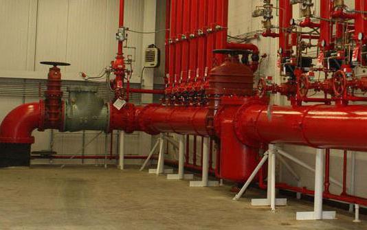
The fire water supply system is not only channel feeding and water supply channels. This is a whole infrastructure of devices, accessories and devices that are not always directly associated with the maintenance of water carrier. Nevertheless, almost all fire water supply systems are formed on the basis steel pipes or their parts connected by welding. The required component of the pipeline is the crane - as optimal material For this part, a wrought iron is used or in extreme cases are used bronze. The crane is designed to connect with fire hoses, if we are talking about mobile systems fire extinguishing.
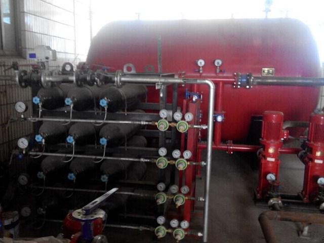
As already mentioned, one of the technological points of maintenance of the water canal is the pump. This can be a pumping station of high pressure, capable of serving at the same time several stationary sprinklers and mobile water supply channels. Also, the composition of the water supply is provided for regulating and shut -ling fittings, switches, tanks, detectors, etc. The configuration of the location of these devices may vary depending on which scheme is implemented directly the fire pipeline in the structure of a particular object. So, there are external and internal methods Promotion accommodation.
Fireman external water supply
The external method of installation and operation is optimal, if we are talking about the extinguishing of large construction objects using special technical means. In particular, most of the systems of this type are oriented on a volume of up to 1000 m3. As for specific types of facilities, the outer fire pipeline is used for almost all production facilities in classes, G and D. Also allowing hanging, terminals, storage facilities.
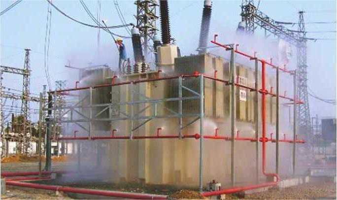
Water consumption in this case is about 10 l / s. This is the average value, since theoretically, the maximum value can reach 35 l / s. However, in the case of residential and public objects, limit the requirements for loads on water supply networks and distribution lines. The level of pressure with which water will be carried out is pre-calculated. For example, the recommended value when used low pressure It is 10 m. As the flood increases, the force may increase in the calculation - 4 m per floor. Despite the attractive powerful indicators, the outer-type fire pipe is not always effective in the fight against internal sources of ignition. Accordingly, in such situations, the internal water supply lines are often used.
Fire inner water supply
The standards of the organization of the internal fire pipeline are defined in the relevant section of SNiP at number 2.04.01-85. This water supply provides fire extinguishing in manufacturing and public buildings, regardless of their categories. The height of the water supply can be 50 m, and the volume to reach 50 thousand m 3. For residential buildings, the inner fire pipeline on average carries out water supply at a speed of 1.5 l / s - provided that the diameters of the sleeves and trunks are adjusted under 38 mm.
It is thanks to a narrow jet that such systems can provide a carrier to large heights. For the same reason, they are inappropriate to use low buildings in the protection of fire. Most often, such structures are entered into hospitals infrastructure, schools, universities, activities, industrial premises.
The main task that the inner fire pipe is performed is to prevent the spread of fire at specific points. Therefore, if in the case of an outdoor water supply, the main goal is to supply mobile lines with sleeves, then the internal complexes are focused on stationary sprinklers integrated into the ceilings of the premises. It can be draincore and sprinkler nozzles with different design Nozzles focused on scattering drops or fog. Such devices are distinguished by construction complexity, but their advantage is the ability to operate in automatic mode.
Check for waterproof
In the process of testing, the system for water production is assessed as far as pressure indicators on the main trunk correspond to regulatory pressure. This check allows you to insure from overloads on the line and prevent accidents. Waterproof tests are held twice a year. Test time is selected, based on the period in which the most active water consumption is observed at the facility. For example, in the summer season. In this case, communication should be checked with minimal pressure in the main central line. This will allow you to evaluate the possibility of working the channel with the least favorable conditions.
In addition to the pressure, the check of the fire water supply also allows you to identify the level of the height of the compact jet segment, the volume of water consumption and the pressure of the valve. But specifically making disparate measurements in most cases is not required, since these indicators are interrelated. For example, the pressure on the main trunk will correspond to the same indicator in the crane. And at least the data on consumption and height of the jet will be put in the standard.
Waterproof check itself is carried out sequentially on the fire crane, which has the greatest removal from the pumping station. If the line falls on the line from several cranes - each of them must be activated. Including adjacent cranes and communications connected to the riser with which the fire pipe is connected. At the same time, the requirements are noted that the pressure should be measured only on the main supply of the crane. Or, as an alternative to convenience, you can control the most highly resorted fire crane system.
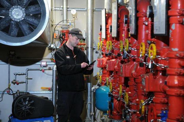
Measuring devices for testing
The pressure is the main measurement parameter, so the pressure gauge will also become the main tool in the test. Usually for such purposes, measuring inserts with pressure gauges are used. The endings of inserts are provided in advance by special heads of couplings.
As for the placement of the device, the position is optimal between the fire sleeve and the valve. Immediately the device manometer is installed on the inset. If there is no direct connection, then you can use a flexible meter hose, which will also allow the degree of pressure on the pressure gauge scale.
Depending on the tasks of the water pipeline, other parameters can also be provided. For example, temperature. But for this it is necessary to use or combined pressure gauges with the thermometer function, or industrial bimetallic devices with a remote measurement sensor.
Checking system elements
In addition to checking the metrological and working indicators of the plumbing fire infrastructure, the technical condition of its components is also also experienced. They are not always tested by the main object of verification as part of a water review, therefore a separate examination fully justifies itself.
The lack of breaks, deformations and defects on the surfaces of the trunk are the main criteria for which the internal fire pipeline is also evaluated in this part. Requirements and for external and for internal systems Initially, it is prescribed that the manual stems the output diameters should be within 13-19 mm. The average permissible value is 16 mm.
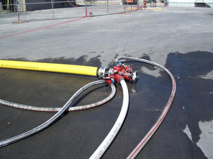
Sleeves are also checked for integrity and size compliance. In particular, the length of the sleeve can be 10, 15 or 20 m. As for diameters, they vary from 51 to 66 mm. The specific stem and sleeves are chosen based on the type of object served and the requirements for fire extinguishing tactics.
By the way, the inspection of the inner fire pipeline also applies to the analysis of the quality of the work of sprinklers, having its own design features. The performers estimate their tightness, water supply quality, the integrity of the element base and the quality of the compounds. Almost every system provides for the presence of water tanks that can be called backup sources. The tanks of this type are checked for the tightness and quality of the connection with the communications of the plumbing lines.
Evaluation and registration of test results
In each case, positive parameters will be different because it can go about individual project water supply. As a basic criterion, pressure indicator is considered. Its value in accordance with regulatory proportions will be overlapped with optimal values \u200b\u200bthat appear in the project solution. In any case, the positive check of the fire station will be supposed only if the integrity of the equipment and its compliance is concrete technical parameters - length, diameter, etc.
After fixing the results of the verification, a special document is drawn up. In particular, the test writes a protocol in which data is entered on the results of testing the potential of water production. This document includes information about the pressure in the barrel and valve. Together with this, the act of fire water supply, which indicates the time and place of testing, as well as information about the building and the maintenance of equipment. The characteristics of tested communications are described in detail - for example, the type of trunk, the material of the sleeve, the sizes of the crane, etc. Both documents should eventually have to sign all members of the Commission who participated in the verification process.
Safety requirements
In the process of testing, the scan participants must comply with the safety rules. First of all, persons who have passed the appropriate instruction on the constructing of fire water supply tools are allowed to the tests. Each participant must have special clothing with water-repellent coating. The characteristics of its tissues must correspond to the loads that the water supply survey is running.
Typically, such events are carried out on special polygons, but in some cases, when it is necessary to evaluate the performance of the system as a whole, the check is inevitably carried out at the site of the operation of the equipment. In such situations, for example, water testing can be performed only at the moments when the submission of the jet does not threaten the passing people and transport.
Inside the building, fire safety of the water supply should also be provided if the infrastructure of the interaction of the source, pump and sprinkler is checked. Since a comprehensive check may assume the fulfillment of a number of team-collapsible manipulations, you should prepare a complete set of tools and accessories suitable for a particular type of tap fittings.
Maintenance requirements
The technical condition in the event that the infrastructure is used regularly, should be checked at least twice a year. Pipes, risers, reinforcement elements, connecting accessories, hoses with trunks, fire cabinets and other devices and devices are exposed to check. If necessary, the service personnel performs repair work, changes the worn parts, updates the lubricating fluids in the pump motor filling and makes structural changes.
It should be borne in mind that the state of the water supply can negatively affect not only the effectiveness of the fire extinguishing function, but also on the safety of the building itself or the premises to which it is attached. For example, under high pressure load, even without a threat of fire, the contour of the pipe can arbitrarily escape from a sloping compound, causing material damage to property.
At the same time, the service of fire water supply affects both the performance of the line as such. Employees evaluate the quality of the pumping station and the stability of water supply from the main source. If necessary, they also make adjustments to the parameters of the pressure and performance of the equipment so that they optimally meet the requirements of fire safety for the current period.
Conclusion
The key to successful verification and efficient operation of the fire station is provided by the design and installation work. Experts determine the rationality of laying contours in one way or another, take into account the potential of hydrants, pumping stations and water supply lines. If conscientious work was performed at these stages, then with a greater likelav, the fire pipeline will demonstrate compliance and regulations on water and technical requirements.
In the future, the quality of operation of the plumbing infrastructure will depend on other factors. For example, as far as the same hydrants are protected in winter. No less acute questions and venue for transport. Near public buildings and production facilities necessarily provide for parking for fire trucks. At the very least, access roads and roads should be prepared to the nearest sources of water supply regardless of the year.
It will be worth it to envisage and the nuances of power supply. Usually, pumping stations Automatic control is operated from the power supply, so the presence of a backup generator will be insured in the event of an emergency stopping of current supply from the central line.