Electrical work of the connection diagram. We draw up and select the correct wiring diagrams for the wiring in the apartment. Optimal outlet locations
Installing wiring in a private house is a laborious process, but nevertheless, even a novice electrician can do it! If you are determined to do all the settlement work yourself and have all the essential tool, or you just want to control a working electrician, then we will look at the whole process from A to Z. To make the technology understandable even for beginners (dummies, so to speak), we will step by step look at how electrical wiring should be done in the house with our own hands.
The process consists of several main steps:
- choice of laying method (open, hidden);
- creating a schema;
- marking work;
- choice of constituent elements;
- direct wiring;
- obtaining permission to connect to the local power grid.
Using the example of a new house, consider how to independently conduct electrical wiring.
Selecting the type of electrical installation
The first thing to start with is to decide on the method of mounting the line. Today, open and hidden type wiring is used. is the fastening of all constituent elements on top finished walls(routes are laid in special cable channels).
The advantage is:
- the damaged area can be repaired without any problems (no need to cut the wallpaper, destroy the plastered walls, etc.);
- easier installation and preparatory work(not needed in the house);
- convenient to add new branching points.
The disadvantages of this installation method are one - very often does not fit into the overall interior of the rooms, as cable channels are not very attractive.
In places for installing junction boxes, switches and sockets, we make round recesses with a puncher with a crown (we select the depth and diameter of the strobe in accordance with the dimensions of the products). Depending on the type of walls, we choose a diamond or pobedit crown (for concrete) or a crown for wood and drywall.

You can see how to make strobes for electrical wiring in the house in the video below:
Step 2 - Attaching Junction Boxes
Boxes and socket boxes are installed in wells (the so-called round strobes). For their installation, it is recommended to use screws with dowels or a layer of asbestos (about 2 mm). After securely fixing the boxes, we move on.

You can clearly see the process of installing the socket box in the following video:
Step 3 - Installing the cable
The gate is cleaned from the remnants of dust, stones and other foreign objects, primed or spilled with water, after which it is necessary to lay the cable in it. For fixing electrical wiring, it is recommended to use plaster or alabaster. Those who do not want to deal with the solution can fix the wire with dowel clamps.
The tacking step is about 40 cm. We talked about the rest in the corresponding article, which we strongly recommend reading!

Step 4 - Connecting outlets and switches
As soon as the plaster completely hardens (in about a day), it must be carefully rubbed with a grater. After that, you can proceed to the installation of sockets and switches.
Obtaining permission to connect to the local power grid
First you need to pass acceptance tests ( technical survey the site where the electrical installation was carried out). If the result turns out to be positive, you will be issued a “Connection Permission Certificate”, on the basis of which the Electricity Owner must connect your residential facility.
The rules for connecting to the network are described in RF PP 861 of December 27, 2004 and its numerous editions (updated until 2015).
The power supply company is obliged to connect to the power grid for objects with a capacity of up to 15 kW, regardless of whether it has such an opportunity. Connection with a dedicated power of up to 15 kW, and a line length of not more than 500 meters costs 550 rubles. For this money you will receive
Parallel- with this method, the elements included in the chain are united by two nodes and are not connected to each other. With such a connection of the elements, even if one of the lamps burns out and breaks the circuit, the rest will not go out, since the current will have “bypass” paths.
Sequential- all elements of the chain are located one after another and do not have nodes. An example of a serial connection is the well-known Christmas tree garland: a large number of light bulbs connected by a single wire. If one burns out, the chain will break and all will go out.

There are three main types of electrical wiring. Let's consider them in detail, since the whole scheme depends on the type chosen.
1. star type sometimes called boxless, or European, type of wiring. Briefly given type can be displayed as follows: one outlet - one cable line to the shield. This means that each socket and lighting point has a separate cable line that goes directly into the apartment panel and ideally has a circuit breaker. What are the advantages and disadvantages of this type of wiring? Plus - first of all, in safety and the ability to control each electrical point. Also, you don't need to install junction boxes. This type of wiring is done when the system is installed " smart House". Minus the "stars" - at least three times the consumption of wiring and, accordingly, labor costs for its installation. In addition, the housing shield becomes the size of an average closet. It can include 70–100 groups of automata, especially if the facility also has information networks. It is difficult to install such a shield on your own, and it is more expensive than usual.
2. Loop type resembles a "star", but differs from it in efficiency. You can depict it like this: a socket - a socket - a socket - an apartment shield or a junction box. Several electrical points are connected in series to one cable, from which a common supply conductor goes either to the apartment shield or to the junction box.
3. Type of wiring in junction boxes- the most common variant. This is how the wiring was done in Soviet time. An economical way that does not require special costs. There is no shield in the apartment at all, it is located on landing. An apartment branch departs from such a common supply "riser". There is a meter and a circuit breaker on it in the shield (sometimes - 1, sometimes - 2-3, rarely more). The supply cable enters the apartment, then with the help of junction boxes - into the premises, approaching each point. We can say that from the junction box, the wiring goes to the "star" points.
In its pure form, wiring types are rarely used. Based on available resources and optionally, a mixed type is usually selected. An example of wiring in a separate apartment.

Two types of wiring: socket - shield ("star") and shield - socket - socket - socket ("loop")
The power cable is included in the apartment shield, where there are several groups of automatic machines and protection devices. In the shield, the common cable is routed into several zones, for example, along living rooms and separately for the bathroom and kitchen with a division into sockets and lighting. The power cable of a separate zone enters the room and is distributed in a box by points. Options are possible here: the cable will go to the sockets with a “loop” or a separate wire will be allocated to each point.

Serial "loop" and parallel in junction boxes

Professional electricians draw up such circuits taking into account all factors. These are the wishes of the owner of the object, that is, what exactly you want to see in an apartment or house. For example, the owner says that the living room should have two groups of outlets, three in each. Plus two walk-through switches and telephone sockets in the amount of three pieces. The electrician, taking into account these data, according to the rules of electrical work, draws up a scheme that takes into account safety parameters, the procedure for performing work, the type of wiring, the dimensions of the gate, etc. Such a drawing is a document and is certified by a special organization.

An example of a schematic diagram of the power supply of an apartment, compiled by a professional electrician
Modern firms providing services for electrical work use computer programs. They are designed specifically for engineering and technical workers (ITR) and home master unlikely to be useful.
To do the wiring yourself, you can draw the diagram yourself. This is done quite simply. To begin with, an apartment plan is depicted, taking into account all sizes. If the necessary documentation is not available, you can take it from the developer, although it must also be kept by the owner of the home.
Then, using special symbols, all the desired points are set: lamps, sockets, circuit breakers, etc. You must not be too lazy and put generally accepted symbols so that other people understand this scheme. There are frequent cases when, after some time, the author of the scheme cannot figure out the mysterious hieroglyphs, which he himself invented. After that, lines are drawn that indicate the wiring. Be sure to indicate on the plan how far from the ceiling or floor the cable is, especially if the wiring is hidden.
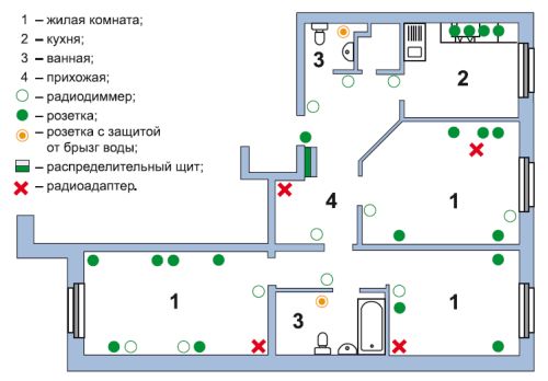
The following is an example of an electrical circuit of an apartment. Lighting wires are shown in different colors, power cables and ground wire. Conventional icons depict fixtures, sockets, switches and junction boxes. Such a scheme is very clear, and according to it you can perform everything necessary calculations. This is necessary in order to know exactly where the wires go in the future. Otherwise, when hanging a picture or a shelf, you can get a drill directly into the cable.
Exist model rules for mounting. They are:
1. The wire is laid only along vertical and horizontal lines at right angles. If there is a desire to cheat and save the cable by running it diagonally, it is better not to do this. In the future, it is very difficult to find this curved path, and getting into it easier with a nail simple.
2. The distance from the wire to the ceiling or floor should be 15 cm. From corners, door jambs and window frames- at least 10 cm. When circling through heating pipes, a gap between them and the wiring should be at least 3 cm.

3. Avoid crossing wires when laying. If this is difficult, then the distance between the cables should be at least 3 mm.
4. To simplify calculations, all sockets and switches should be at the same height. Usually, switches are installed to the left of the door at a height sufficient to touch them with a lowered palm, that is, 80–90 cm. Sockets are mounted at a height of 25–30 cm. However, in the kitchen and in the case of connecting high-hanging electrical appliances, this distance may be and others. It is best if the wire to the switches will go down from above, and to the sockets from below - this is what most electricians do.
5. The length of the conductor coming out of the electrical point should be 15–20 cm. This is done for the convenience of mounting points with a hidden type of wiring. If she open type, then the length of the conductor may be less: 10–15 cm.
The ends of the cores of wires that go into electrical points must be insulated with electrical tape. Armed with a drawing, you can begin to mount the wiring.
For any repairs in an apartment, a private house or a country house, as well as a breakdown of any electrical wiring element, you need to know exactly where the wires go. Otherwise, this may lead to additional issues associated with the search for electrical cables disguised in the wall or, even worse, getting the tool into a live wire. In this case, it is desirable to have a wiring diagram. But as often happens, it is not at hand, because when buying your own home, no one is interested in this documentation. Therefore, it is desirable to understand various options power supply, as they are standard in multi-apartment buildings.
Wire connection options
A person who understands what awaits him in the process of independently drawing up a wiring diagram or directly performing work on installing sockets, switches and light sources in own apartment with his own hands he must know the main ways in which electrical circuits are connected.

If the homeowner is completely unaware of the arrangement of electrical circuits, then all installation work in an apartment it is better to trust professional electricians who, in a short time, will draw up a clear plan that includes even the smallest details, which will save on the purchase Supplies.
Video: cable laying diagram in the house
How electrical wiring is done
The choice of scheme should be made with full awareness of the matter. First of all, this is due to the safety rules for using electrical circuits. Today there are three main wiring options.
- The most popular way to lay wiring is to connect all the constituent elements of the network using distribution boxes. Such a scheme provides for the installation of a shield on the landing in a specially equipped niche, and not in a residential area. In the shield there is a device for monitoring the consumed electricity and several bags. The input of electricity to the apartment is carried out by means of a cable, the wiring of which is carried out through the rooms using distribution boxes.
- The wiring diagram using the “Star” method implies that each element is connected by a separate line connected directly to the shield through an automatic toggle switch. With such a wiring, the consumption of wires, physical work and the cost of the project as a whole significantly increase. But having evaluated all the advantages and disadvantages, it becomes clear that all costs are justified, since the system provides the ability to fully control each consumer separately.
- Similar to the previous version of the electrical wiring is the scheme - "Loop". In this version, there is only one distinguishing feature, which consists in connecting several consumers to one cable. This reduces the amount of installation work and consumables, which leads to a reduction in the cost of the project.
In most cases, the wiring diagram provides for a combination of several cable laying methods at the same time. At the same time, it is very important to think through everything to the smallest detail, so that in end result achieve maximum efficiency and safety of the electrical circuit.
Standard scheme
 It is advisable to implement all ideas for arranging electrical circuits before starting installation work in a detailed diagram laid out on a sheet of paper. At the same time, it is important to take into account the layout of each individual room, which will allow you to calculate the number of distribution groups and power grid elements. For convenience, each group can be performed as a separate scheme.
From practice it has been found that maximum efficiency wiring is achieved by combining consumption sources into several groups, each of which is connected to a separate automatic bag. Thanks to this technical solution, further repairs and maintenance are facilitated. electrical network without the need to de-energize the entire apartment. In addition, the connection of all consumers to one line is possible only if there is a cable with a large cross section, which is able to withstand the increased load that occurs when all electrical appliances in the apartment.
When placing the shield directly in the living room, it becomes possible to connect electrical appliances to individual machines. This greatly increases the efficiency and safety of using the electrical network. But, in that case, why such a scheme is not widely used? Everything is quite simple - this option for connecting devices to the network alternating current significantly increases the cost of implementing the project. Therefore, consumers are divided into the following groups:
- lighting group of living quarters and corridor;
- supply of electricity to the rooms;
- power supply in the kitchen and hallway;
- supply of light and electricity to the bathroom and bathroom. Wherein this group implies increased danger due to constantly high humidity;
- if the kitchen is equipped with an electric stove, then its connection must also be carried out separately.
 To ensure maximum safety of electrical installations, each group must be equipped with an RCD - a special protective device, which is nothing more than a differential circuit breaker at maximum current values. Also such protective devices It is necessary to equip the wiring in the bathroom and in the kitchen.
After the final formation of the main groups, it is necessary to distribute in what places consumers will be placed, such as electric stove, water heater, air conditioner, etc. At the next stage, the marking of the installation of switches, junction boxes, lamps and sockets is carried out. In this case, all the elements must be included in the wiring diagram, based on which, you can calculate the number of wires.
It is very important that circuit diagram electrical wiring was drawn up in several copies, one of which must be saved for the future. After all the little things are taken into account, you can draw up a detailed final drawing in accordance with the exact plan of each room.
All installation points electrical elements are put on the diagram in accordance with the generally accepted notation and are connected by lines denoting the wires. To improve the readability of the diagram, it is desirable to designate different groups of wires in different colors.
Scheme in without fail should include all dimensions of the premises, distances from the electrical panel to sockets, switches and lighting sources, etc. Such detailed plan will allow in the shortest possible time to carry out high-quality installation work and the calculation of all necessary consumables, which will make it possible to plan expenses.
Video: electrical wiring diagram in the apartment
 In order to correctly make an apartment wiring diagram, you should know some important requirements for laying wires in residential buildings.
- The bathroom is not supplied with outlets, except for one connected via a transformer to turn on low voltage appliances such as an electric shaver.
- It is unacceptable to connect the grounding of the socket to the zero terminal. It is also strictly forbidden to ground the wiring elements to the battery or water supply. It is unsafe for the tenants of the apartment.
- If a stove is installed in the kitchen that is connected to an alternating current network or other powerful consumers, then the main machine must be of a large denomination so that false positives do not occur.
- Wiring must be carried out only in a vertical or horizontal direction.
- Reversing the direction of the wiring can lead to the risk of a nail or drill hitting a live wire during repairs. Crossing of cables is also unacceptable.
- It is important that electrical wires run 15 cm from the surface of the floor or ceiling, as well as window and door frames And outside corners premises.
- The distance from the heating or water pipes should not be less than 3 cm. The wiring to the socket should come from the bottom, while to the switch from the top.
It is desirable that all do-it-yourself sockets and switches are located on the same level. So, for sockets, the acceptable height from the floor is 30 cm, while for switches they retreat from 80 cm to 1 m. Naturally, if necessary, these parameters can be changed to suit the needs of apartment residents.
How to make do-it-yourself wiring
For laying electrical wires in the apartment, you must strictly follow the prepared scheme. At the same time, there is a certain sequence of doing such work with your own hands.

For the correct connection of wires, it uses three different methods - using terminals, soldering or twisting, which can be viewed on the video. The first two are considered the most effective in use, since they are considered the most reliable and have a high degree of security, although they are more difficult to do with your own hands.
Video: electrical wiring
Which wires to choose
 To properly make the wiring in the apartment, you need to buy suitable wires. Wherein copper cable is considered the best wire for the simple reason that it has maximum flexibility, is less brittle and has a high current conductivity. It is also more convenient to mount it, unlike its aluminum counterpart.
In apartments, in most cases, wires are laid with two or three cores with a cross section of 2.5–3 square mm for sockets and 1.5 for switches and lamps. For more powerful consumers a separate line is laid with wires over 3 mm square, which will allow them not to overheat.
The wiring diagram may well be drawn up and implemented independently. But the responsibility for the quality of its work and the safety of residents will lie with the person who carried out the installation work. Therefore, at least minimal knowledge in this area is welcome.
Video: how to choose the right cable section
Electricity is a serious and responsible business. If you are going to do all the work yourself, you need to do everything very carefully and diligently. Correct wiring electrical wiring in a private house is a guarantee of safety, because according to statistics, 70% of fires occur due to electrical faults. If you are not confident in your abilities, it is better to entrust the work to specialists, only proven ones.
Action plan
Wiring in a private house is done before the start finishing works. The box of the house has been kicked out, the walls and roof are ready - it's time to start work. The sequence of actions is as follows:
- Determining the type of input - single-phase (220 V) or three-phase (380 V).
- Development of the scheme, calculation of the capacity of the planned equipment, submission of documents and receipt of the project. Here it must be said that not always in the technical conditions they will determine the power you declared, most likely they will allocate no more than 5 kW.
- Selection of components and accessories, purchase of a meter, automatic machines, cables, etc.
- Entering electricians from the pole into the house. It is carried out by a specialized organization, you need to decide on the type - air or underground, install an input machine and a counter in the right place.
- Install a shield, bring electricity to the house.
- Laying cables inside the house, connecting sockets, switches.
- Ground loop device and its connection.
- Testing the system and obtaining an act.
- Electrical connection and operation.
This is only a general plan, each case has its own nuances and features, but you need to start with getting specifications electrical connection and project. To do this, you need to decide on the type of input and the planned power consumption. It must be remembered that the preparation of documents can take up to six months, so it is better to submit them even before the start of construction: two years are given to fulfill the technical conditions. During this time, for sure, you will be able to drive out the wall on which you can put the machine and the counter.
How many phases
IN a private house single-phase voltage (220 V) or three-phase (380 V) can be supplied. According to the energy consumption standards for a private house for a single-phase network, the maximum consumption for a house can be 10-15 kW, for a three-phase network - 15 kW.
 Three-phase input is needed only when you need to connect powerful equipment powered by 380 V
 So what's the difference? The fact that powerful electrical appliances can be directly connected to a three-phase network - electric stoves or heating boilers, ovens and similar equipment. However, the input requirements and wiring of the 380 V network are much tougher: the voltage is higher, there are more chances of serious injury. Therefore, if your house is no more than 100 square meters, and you do not think to heat it with electricity, it is better for you to use 220 V.
Making a plan and receiving a project
Having decided on the type of input, you can begin to develop a plan for the electrification of the house. Take a house plan on a scale, and draw where the equipment will stand, figure out where to place sockets and switches. At the same time, it is necessary to take into account where what large-sized furniture will stand, and where it can be rearranged so that sockets and switches are not placed in these zones.
On the plan, you will need to put everything lighting: chandeliers, sconces, floor lamps, lamps. Some of them will need switches, some will need sockets. Then you will need to figure out which devices in each room will need to be turned on.
For example, the kitchen has a lot of appliances that work constantly. It definitely needs sockets. There is also a technique that turns on periodically. All this is applied to the plan, the optimal location of the inclusion points is determined. The same approach is in each of the rooms.
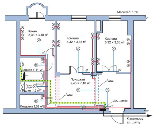
 The result of the design of electrical wiring in a private house. You should also get a similar scheme
 Determining the total power
Having decided approximately what equipment will be in your house, sum up its power. Average capacities can be taken from the table: there is probably no technology yet. Moreover, where there is, take into account the starting loads (they are much higher). Add about 20% of the stock to the amount found. The result will be the required power.
You indicate it in papers submitted for obtaining permission to connect electricity to the site. If you are allocated the declared capacity, you will be very lucky, but you should not hope for it. Most likely, you will have to invest in the standard 5 kW - the most common electricity limit for a private house.
 Average values of the power of devices for calculating the total load on the wiring of a private house with your own hands
 Breakdown of consumers into groups
All these consumers (this is the term of professionals) - lamps, spotlights, switches, sockets - are divided into groups. A separate branch is diluted with an electrician for lighting fixtures. Usually one is enough, but this is not a rule, it may be more convenient or more expedient to make two branches - for each wing of the house or for each floor - depending on the type and configuration of the building. Just in a separate group stands out the lighting of the basement floor, utility rooms as well as street light.
Then they are divided into groups of sockets. How much you can "plant" on one wire - depends on the diameter of the wire used, but not very much - three to five, no more. It is better to allocate a separate power line for connecting each powerful device: this is more reliable in terms of fire safety, and will contribute to a longer operation of the devices.
As a result, you can have three to seven lines going to the kitchen - here the equipment is the most and most powerful too: for an electric boiler, an electric stove, separate lines are needed unconditionally. Refrigerator, microwave, electric oven, washing machine it is also better to "plant" separately. Less powerful blender, food processor, etc. can be included in one line.
 Designing electrical wiring in a private house: we count the number of groups and plan what to connect where
 Usually two or four lines go to the rooms: in a modern dwelling and in any room there is something to plug into the power grid. One line will go to lighting. On the second there will be sockets in which you will need to turn on the computer, router, TV, phone charger. All of them are not very powerful and can be combined into one group. If you plan to install an air conditioner or will turn on an electric heater, you need separate lines.
If a private house is small - a summer house, for example, then there can be two or three groups in general: it is for all lighting fixtures, the second - for the street and the third - for all internal sockets. In general, the number of groups is an individual matter and depends most of all on the size of the house and the amount of electrical equipment in it.
 The wiring plan can be quite small if the house is small.
 By the number of groups received, the number of machines on the switchboard in the house is determined: to the received number of groups, add two to four for development (suddenly you forgot something important, or you need to turn on something powerful new, divide the group that is too large or far apart into two, etc.).
By the number of groups, the switchboard and the number of machines in it are selected: for each group there is a separate machine. If a private house is large - on several floors, it makes sense to put more powerful machines on each floor, and connect group machines to them.
Where to put the shield
The place of installation of the shield is not standardized by the regulations. There are only restrictions on the distance from the pipelines, it must be at least 1 meter away. Any pipes are taken into account: water supply, heating, sewerage, internal drains, gas pipelines and even gas meters.
There are no restrictions on premises. Many put a shield in the boiler room: since the technical room, it is reasonable to collect all communications here. The receiving authorities make no claims. Sometimes it is more convenient to place the shield near front door. If the protection class meets the requirements, there should be no complaints.
Selection of cables and accessories
The standard wiring diagram of a private house today includes two machines. One - input - is installed before the counter, usually on the street. It and the counter will be sealed upon commissioning. The second RCD machine is placed in the house in front of the shield.
The tripping (shutdown) current of these devices is selected so that the machine installed in the house is turned off first (its current value is slightly less). Then, in case of emergency operation, you will not need to climb under the roof.
 Typical scheme wiring of a private house: there can be many different groups
 If the calculated load is less than 15 kW, the input machine is set to 25 A. The meter is selected accordingly. With a higher power consumption, it will be necessary to install a transformer, its parameters and the parameters of all equipment will be indicated in the project.
Recently, when connecting a private house to the mains, it is required to install a meter and a machine on the street. This requirement is not legally confirmed by anything, it’s just that it’s easier for the electric service to control consumption. If you want, you can fight, if not - choose a counter and an automatic machine in a case with increased dust and moisture protection - a protection class of at least IP-55. For installation inside a building, protection should be less - IP-44, and the price will be lower accordingly.
Cable selection
For electrical wiring in a private house, it is better to use cables, not wires. They have at least twice the insulation, so the laying requirements are not so strict, and it’s safer to use them. All internal wiring in a private house must be made with protective earth. Previously, there were no such requirements, but now many electrical appliances have three-pin plugs and for safe work require grounding. Therefore, the cable must be three-core.
IN electrical cables conductors are made of copper or aluminum. Although aluminum is cheaper, it is used less often: it is hard, breaks more often, and is more difficult to work with. With self-wiring in a private house and lack of experience, this can become a problem. Moreover, in wooden houses internally, it cannot be used at all.
Determining the cross section of the cores
After you have decided on the material, you can choose the diameter of the cable cores. They do this depending on the planned load on the line according to the table.
 Calculation of electrical wiring - the choice of the cross section of the cable cores is carried out according to this table
 The cross section of the core is selected by current or by the power of all consumers connected to one machine. This is where the house electrification plan comes in handy again, where you have drawn consumer groups. Count the sum of the currents or powers of all devices and select the desired cross section of the wires according to the table.
How to use the table? If you decide to lay copper wires, the input voltage is 220 V, then the left part of it, the corresponding column, is suitable for internal wiring. It will compare the found power of all consumers connected to the group (it is easier to find and calculate it).
In the part dealing with copper wires stacked in trays, voids, channels, in the "220 V" column, find the nearest higher value. On this line, move to the right to the column “Section, sq. mm". The figure indicated here will be the required core size. From conductors of this diameter, it will be necessary to make electrical wiring from the machine to sockets or switches.
In order not to get confused when counting and laying, mark the conductors of the same diameter on the plan certain color(Write down so you don't forget what color you marked). After the diameter is determined for all consumer groups, the length of the required cables for each size is calculated, a margin of 20-25% is added to the figures found. You have calculated the wiring for your house.
Shell type selection
There are certain requirements for the type of sheath only when laying electrics in wooden houses: it is recommended to use triple (NYM) or double (VVG) cable insulation there. Houses made from less combustible materials can use any kind of insulation.
The main thing is that it be intact, without cracks, sagging and other damage. If you want to play it safe, you can use conductors with enhanced protection. This makes sense in rooms with high humidity (kitchen, bathroom, swimming pool, sauna, etc.).
Choice of sockets and switches
For some powerful devices, sockets are selected according to the maximum (starting) current. For other low-power consumers, they are standard. You need to know what they are:
- External - when the body sticks out of the wall. They are easier to install: a substrate is attached to the wall, and a socket is attached to it from above. But few people use such models now, even in summer cottages. The reason is aesthetic: not the most attractive sight.
- Internal. Under the electrical part, a recess is made in the wall, it is installed and walled up in it mounting box. Inside this box is inserted the electrical part of the socket or switch.
It is the internal electrical sockets and switches are most commonly used today. They are designed in different style, painted in different colors. They are selected mainly to match the finish, and if this is not possible, they are put in white.
DIY wiring
Modern construction trends include concealed wiring. It can be laid in grooves specially made in the walls - strobes. After laying and fixing the cables, they are covered with putty, comparing with the surface of the rest of the wall.
If the erected walls will then be faced sheet materials- drywall, GVL, etc., then strobes are not needed. The cables are laid in the gap between the wall and the finish, but in this case - only in corrugated sleeves. The sheath with laid cables is fastened with clamps to the structural elements.
 How should internal wiring be laid? In a private house, when arranging with your own hands, you must follow all the rules
 When laying, you need to remember that the internal wiring of a private house is done in accordance with all the rules and recommendations. This is the only way to guarantee safety. The basic rules are:
- wiring only vertically and horizontally, no rounded corners or beveled routes;
- all connections must be made in mounting junction boxes;
- horizontal transitions must be at a height of at least 2.5 meters, from them the cable goes down to the outlet or to the switch.
A detailed route plan, similar to the one in the photo above, must be saved. It will come in handy during the repair or modernization of wiring. You will need to check with him if somewhere nearby you need to ditch or make a hole, hammer in a nail. The main task is not to get into the cable.
Wire connection methods
A large percentage of wiring problems stem from poor wire connections. They can be done in several ways:
- Twisting. Only homogeneous metals, or those that do not enter into chemical reaction. It is impossible to twist copper and aluminum categorically. In other cases, the length of the bare conductors must be at least 40 mm. Two wires are connected to each other as tightly as possible, the turns are stacked one next to the other. From above, the connection is wrapped with electrical tape and / or packed with a heat shrink tube. If you want the contact to be 100%, and the losses to be minimal, do not be too lazy to solder the twist. In general, according to modern standards, this type of wire connection is considered unreliable.
- Connection via terminal box with screw terminals. Metal terminals are soldered in the case made of heat-resistant plastic, which are tightened with screws. The conductor, stripped of insulation, is inserted into the socket, fixed with a screw, using a screwdriver. This type of connection is the most reliable.
- Connecting blocks with springs. In these devices, contact is provided by a spring. A bare conductor is inserted into the socket, which is clamped by a spring. And still, the most reliable connection methods are welding and soldering. If it is possible to make the connection like this, we can assume that you will not have problems. At least with connections.
- Do-it-yourself installation of electrical wiring in a house requires careful fulfillment of all requirements. This is a guarantee of your private security and the security of your private property. After the wires from the machine to the connection point of the socket or switch are laid, they are checked for integrity with a tester - they ring the wires among themselves, checking the integrity of the conductors, and each individually to the ground - checking insulation is not damaged anywhere. If the cable is not damaged, proceed with the installation of the socket or switch. Having connected, they check it again with a tester. Then they can be started on the appropriate machine. Moreover, it is advisable to immediately sign the machine: it will be easier to navigate. Having finished the electrical wiring throughout the house, having checked everything on their own, they call the specialists of the electrical laboratory. They check the condition of conductors and insulation, measure grounding and zero, and give you a test report (protocol) based on the results. Without it, you will not be given a commissioning permit.
During work on electrical engineering, a person may encounter the designations of elements that are conventionally indicated on wiring diagrams. The variety of electrical circuits is very wide. They have different functions and classification. But everything graphic symbols V conventional form are reduced to one form, and for all schemes the elements correspond to each other.
Wiring diagram is a document in which connections are indicated constituent elements different devices, consuming electricity, among themselves according to certain standard rules. Such an image in the form of a drawing is intended to teach specialists in electrical installation so that they understand from the diagram the principle of operation of the device, and from which constituent parts and elements it is assembled.
The main purpose of the wiring diagram is to assist in the installation of electrical devices and appliances, simple and easy detection of a malfunction in the electrical circuit. Next, we will understand the types and types of wiring diagrams, find out their properties and characteristics of each type.
Electrical diagrams: classification
All electrical circuits, like documents, are divided into kinds and types. According to the relevant standards, you can find the division of these documents by types of schemes and types. Let's analyze their detailed classification.
The types of wiring diagrams are as follows:
- Electrical.
- Gas.
- Hydraulic.
- Energy.
- divisions.
- Pneumatic.
- Kinematic.
- Combined.
- Vacuum.
- Optical.
Main types:
- Structural.
- Mounting.
- United.
- Locations.
- Are common.
- Functional.
- Fundamental.
- Connections.
Considering the electrical circuits, the listed designations, by the name of the electrical circuit, determine the type and type.
Designations in wiring diagrams


In the modern period, both domestic and imported elements are used in electrical work. Foreign parts can be introduced a wide range. On the diagrams and drawings, they are also indicated conditionally. It describes not only the size of the parameters, but also the list of elements included in the device, their relationship.
Now you need to figure out what each specific electrical circuit is intended for, and what it consists of.
circuit diagram
This type is used in distribution networks. It provides full disclosure of the operation of electrical equipment. The drawing must indicate the functional units, their connection. The scheme has two types: single-line, full. The single-line diagram shows the primary networks (power). Here is her example:

A complete version of the electrical circuit is depicted in elemental or expanded form. If the device is simple, and the drawing includes all the explanations, then a detailed plan will suffice. At complex device with control circuit, measurement, etc., optimal solution will display all nodes on separate sheets, to avoid confusion.
There is also a circuit diagram, which shows a copy of the plan with the designation of a separate node, its composition and operation.
Wiring diagram
Such electrical diagrams are used to explain the installation of any wiring. They can depict the exact position of the elements, their connection, the characteristics of the installations. The wiring diagram of the apartment will show the placement of sockets, lamps, etc.

This scheme guides electrical work, gives an understanding of all connections. For mounting home appliances such a scheme is better suited for work.
United scheme
This type of schema includes different types and types of documents. It is used in order not to clutter up the drawing, to indicate important circuits, features. More often, combined schemes are used in industrial enterprises. For home use, it hardly makes sense.

Having studied conventions by preparing necessary documentation, it is not difficult to understand the operation of any electrical installation.
Assembly order according to the electrical diagram
The most difficult thing for an electrician is to understand the interaction of elements in a circuit. You need to know how to read and assemble a circuit. The assembly involves certain rules:
- During assembly, you must be guided by one direction, for example, clockwise.
- It is better to start by dividing the circuit into parts if there are many elements and the circuit is complex.
- Start assembly from the phase.
- At each assembly step performed, you need to assume what will happen if in this moment apply voltage.
After the assembly is completed, a closed circuit must necessarily form. For example, let's analyze the connection at home of a chandelier, consisting of 3 shades, using a double switch.
First, let's define the order of the chandelier. When you turn on the 1st key, one light should light up, if you turn on the 2nd key, then the other two. According to the diagram, 3 wires go to the switch and the chandelier. Two wires come from the network, phase and zero.
We determine and find the phase with the indicator, connect it to the switch without interrupting zero. We connect the wire to the common terminal of the switch. From it will go 2 wires for 2 circuits. Connect one of the wires to the lamp socket. We derive the second conductor from the cartridge, connect it to zero. One chain completed. To check, click the first key of the switch, the lamp is on.
We connect the 2nd wire from the switch to the cartridge of another lamp. From the cartridge we connect the wire to zero. If you press the switch keys in turn, different lamps will light up.
Now let's connect the third lamp. We connect it in parallel to any lamp. In the chandelier, one wire became common. It is made distinctive in color. If your wires are all the same color, then in order to avoid confusion, it is necessary to use an indicator during installation. To connect a chandelier usually does not require much work, since this circuit is not particularly complicated.