General purpose fire fighting vehicles. Fire trucks. Definition and classification
Fire truck layout
General requirements. Fire trucks are based on trucks general purpose consisting of three main parts: engine, chassis and body.
Most cars are equipped with piston carburetor engines or diesels. The engines are often located in front of the cab. On the chassis for some aerodrome fire trucks, the cabins are located in front of the engine.
The chassis integrates the support system, transmission, axles, suspension, wheels, steering and braking systems. They can be all-wheel drive (4x4; 6x6) and non-four-wheel drive (4x2; 6x2; 6x4).
The truck body, placed on the chassis frame, consists of a platform for the load and the driver's cab.
To create fire engines on the chassis of trucks, a fire superstructure is being erected. Depending on the purpose of the fire engine, the superstructure may include a cabin (salon) for a combat crew, various mechanisms, tanks and tanks for OTV, fire-fighting equipment.
The fire superstructure is therefore the cargo to be transported. The mass of this load is constant, i.e. the fire engine has no idle runs. By definition, it is operated in a transport mode and in a combat mode on fires.
The layout of fire trucks should be such that its technical capabilities are realized in transport mode, in conditions that limit maneuvering, and in stationary modes when exposed to dangerous factors fire.
The technical level and perfection of the design of the fire superstructure, as well as the rationality of its layout with the base chassis, must ensure the implementation of all the requirements for fire trucks. In this case, the layout should:
not to reduce the safety performance of the base chassis;
to ensure, in the shortest possible time, the implementation of hostilities with the safety of personnel;
meet the labor protection requirements of firefighters and the environment.
All of these requirements will be considered in relation to tank trucks. This is due to the fact that they constitute the bulk of the PM, the AC are equipped with the most numerous combat crews. ACs transport displaceable and non-displaceable cargo. More than 99% of all fires are extinguished combat crews AC.
Some features of layouts of other types of PA will be considered when describing their designs.
Features of AC layouts. The layout of the AC provides a rational mutual arrangement of the superstructure elements and units of the base chassis. The possibility of the most effective implementation of the technical capabilities of the AC depends on its perfection. It mainly depends on the number of combat crews, as well as the mutual arrangement of containers for fire extinguishing agents and a fire pump. The latter will determine the layout of the compartments for fire-fighting equipment.
Requirements for the layout of the AC are formulated by the customer. Its analysis is also important for the consumer.
Two features are important for AD layouts.
First feature, which is important for all PA, is the placement of the crew compartment behind the cabin of the base chassis. Second feature is that the placement of the water tank essentially determines the entire layout.
The placement of the tank can be carried out along or across the longitudinal axis of the base chassis (Fig. 7.20). It also determines the capabilities and limitations of the PN and PTV layouts. So, with the transverse placement of the tank, the fire pump can only be installed in the rear in the aft pump compartment.
Rice. 7.20. Classification of AC layouts
The layout of the salons. Depending on the size of the combat crew, the AC, like other PAs, can have landing formulas 1 + 2; 1 + 5; 1 + 8. Each of them has its own interior layout. In many PAs and some ACs, the cab of the base chassis is used (Fig. 7.21, a). In the AC there can be salons with one (Fig. 7.21, b) or two rows of seats. In the salons, it is possible to place a RPE or install a fire pump (Fig. 7.21, b).
A slightly different layout of the AC on the KamAZ chassis (Fig.7.21, G). The crew cabin is separated from the driver's cabin by a gap With... In addition, the compartments 4 can be in the middle and aft.
The steps for access to the salon are arranged at a height that allows small firefighters to use them freely. The dimensions of the cabins of salons, their doors, and the seats are determined based on the height of tall firefighters.
V 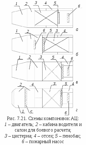 All connected parts of the passenger compartment must have seals that prevent dust, precipitation and heat loss from entering the cab. One or more fire extinguishers, as well as a first aid kit, are placed in the cabin. The equipment should be located so that it excludes the possibility of its spontaneous movement when the vehicle is moving, and sharp corners do not injure firefighters.
Vessels for OTV. The AC has water tanks and foaming agent tanks. Tank capacity and shape have a large impact on the layout and traffic safety.
Traditionally, in our country, tanks were arranged along the longitudinal axis of the base chassis. At ACs with a large capacity of tanks, their transverse arrangement began to be used (Fig. 7.21, v, G). This arrangement allows a more rational distribution of the PA mass along the axes, which in the case of an all-wheel drive chassis provides a more uniform implementation of traction forces on the wheels and improves the controllability of the AC.
Large-capacity tanks in cross-section have rectangular shape... Compared to other shapes (round or elliptical) in this case, the height of the center of mass is significantly reduced. N... This factor improves the safety of movement of the AC on a slope or when turning, since in this case one of two conditions must be met, respectively:
Tg β ≤ V / 2H or v ≤  , (7.7)
where β is the slope angle; V- the track of the AC base; N- height of the center of mass of the AC;
R- the minimum turning radius of the AC; g- acceleration of gravity.
Attitude K = 2B / H are called the coefficient of stability of the car against rollover... With a given track V its value depends only on N... The larger it is, the smaller the angle β can be overcome and the turn can be made at a lower speed.
Depending on the degree of filling of the tank TO decreases by
8 - 10%. Therefore, it is necessary to fill the tank with water after extinguishing the fire. This is also required by the BUPO to ensure the combat readiness of the AC.
Unlike trucks, fire tankers carry shifting loads. In the AC, such a load is water. Her fluctuations have big influence on traffic safety. The damping of fluid vibrations is carried out by breakwaters.
Breakwaters are partitions installed across the tank, perpendicular to its longitudinal axis. The partition area should be up to 95% of the area cross section tanks. The damping of fluid vibrations by the breakwaters occurs more intensively if they are set at an angle of 30 - 35 o with an inclination towards the stern. In AC with a transverse arrangement of the tank and foam tanks, the breakwaters are installed along the axis of the vehicle. Damping of fluid vibrations can also be carried out with a spongy filler, for example, based on polyurethane.
Fire pumps. In world practice, front, middle and rear placement of pumps is used. Front mounted mainly gear pumps are used on low power, lightweight tank trucks. In our country, the prevailing distribution is received layout diagrams with rear placement of pumps (Fig. 7.21).
Layout diagrams with a middle arrangement of pumps have a number of advantages: the conditions for pump control are improved, the design of the transmission is simplified, which makes it possible to reduce not only its mass, but also the height of the center of mass; there is no need to specially heat the pump. However, this layout also has significant flaws. First, the risk of injury to personnel in the cockpit increases in the event of an accident. Secondly, the withdrawal of the suction nozzles to the sides makes the water intake less convenient than in the case of a layout with a rear-mounted pump.
The layout of the pump must be capable of being controlled by firefighters of any size. The same requirement must be met by the location of drain taps, taps for switching on an additional engine cooling system, if any.
The body of the AC. In the bodies are placed tanks for OTV, pumps with water-foam communications, drives for their control and fire-fighting equipment of the PTV. The bodies are assembled from various parts, depending on the adopted method of positioning the water tank. If the tank is placed along the chassis, the body is made of two all-metal frameless pedestals. They are bolted to the tank brackets. The pedestals inside are divided into compartments in which the PTV is located.
In various designs of the AC on their board, the bollards can be
2 - 4 compartments. The compartments are closed from the outside with doors with locks. The doors are hinged. Doors can be made according to the scheme, opening upwards with spring-loaded telescopic struts or curtain type.
The space between the bollards and the rear bottom of the tank is used for the pump room. In the case of an average placement of the pump in the aft part, a compartment for the fire-fighting water is formed.
The placement of compartments for anti-tank weapons and their attachment affects the duration of combat deployment. The difference in the placement and fastening of the PTV can be traced in Fig. 7.22, characterizing the time of its removal and laying of the hose line with the first barrel. From this figure, it follows that it is necessary to place the compartments and fix the PTV in them so that it is equally accessible to firefighters of various heights. Its fastening should allow removal in a minimum time.
In modern AC, the compartments relative to the accessibility zone for firefighters of various heights are placed in different ways (Fig. 7.23). This figure shows Availability Zones ab(dimensions 740 and 1970 mm), the assessment is indicated in points of its various parts. For a number of ACs, the location of the compartments is not very good.
Depending on the location of the tank, the compartments can be located along the sides of the body (7.24, a) or along the sides, but only at the stern of the AC (7.24, b). In the first case, there is more room for access to the machine and compartments. In the second case, the entire PTV is concentrated more compactly. PTV in compartments of this type is located in drawers and on shelves.
O 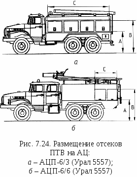 it is obvious that in this case it is necessary to carry out more precise duties by firefighters so that they do not interfere with each other. In addition, drawers for PTV are retractable.
Consequently, an additional operation appears to pull out the drawers and fix them in an inclined position. With this arrangement, part of the fire-fighting equipment is located in drawer at the top of the pump compartment. This placement of the PTV is less convenient than in the case when the compartments are located along the sides of the AC.
Justification of the choice of AC for the garrison of the GPS. The requirements for the AC and the features of their layout are set out in the standards fire safety... They are the basis for the development of technical specifications for the production of new ACs or their modernization. They are justified by the specialists of the State Border Service. Manufacturing requirements are being implemented. Knowledge of these requirements, implemented in the design of the AC, is also important when justifying the choice of fire trucks for the garrisons of the GPS.
The rational order is as follows:
1. The territory is estimated according to natural and climatic conditions.
3. The state of the fire department is checked. water supply network and the presence of natural and artificial water sources in the region is determined.
On the basis of the foregoing, the requirement for the chassis of the AC, the capacity of the water tank is substantiated. These factors will also determine the number of combat crews. It is also necessary to take into account the structure of the existing AC fleet both in terms of chassis and type of engines. Unification of AC, prevention of their multi-brand character will contribute to better organization keeping them in a state of technical readiness and ensuring their maintenance and repair.
7.6. Additional electrical equipment
Fire trucks follow fires at high speeds, operate at different times of the day, often with insufficient lighting of objects. All this requires a high information content of the PA, its adaptability to use in different time days. This necessitates the need for special, additional equipment.
Additional electrical equipment includes:
Alarm devices providing information about the movement of the PA;
External lighting, lighting of workplaces and compartments of a fire engine, ensuring the work of firefighters at night;
Duplicate instrumentation and starter starting system from the pump room;
Heating of the crew cabin.
The electrical equipment of the AC manufactured by Russian enterprises is identical. Therefore, we will consider it using the example of the most massive ACs.
Optional equipment AC-40- (131) 137. The location of additional equipment is shown in Fig. 7.25.
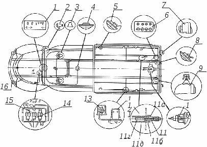
Rice. 7.25. Additional equipment for the fire-fighting tanker АЦ-40 (131) 137:
1
- driver's instrument panel; 2
- spotlight headlamp; 3
- signal lights; 4
, 5
and
8
- lighting shades; 6
- pump room instrument panel; 7
- rear lights;
9
- rear light; 10
- vacuum valve illumination lamp; 11
- a sensor for determining the amount of water in the tank; 12
- switches of compartments of a body; 13
- diodes;
14
- bimetallic breaker; 15
- fuse box;
16
- fog lights
Topic 5: General purpose fire vehicles.
Literature used for the lesson:
Fire fighting equipment: fire trucks, device and application. (V.V. Terebnev, N.I. Ulyanov, V.A.Grachev) Moscow 2007, educational posters (methods of supplying fire extinguishing materials);
№ Educational questions. Time. Content of educational questions.
1. Introductory part. 5 Interrogate HP on the previous topic. Bring the topic, purpose and method of conducting the lesson. Questions:
Define a general purpose user agent
TTX AC-5.0-40 (43253) 22VR
Special fire trucks are designed to carry out special work in a fire. Depending on the purpose and nature of the work performed on fires, special fire trucks can be conditionally divided into two groups: providing fire extinguishing control (headquarters) and ensuring combat operations (ladders, rescue vehicles, gas and smoke protection service vehicles, sleeve vehicles, etc.).
2.1 Main part
FIRST AID FIRE CARS. 70
First aid firefighters are designed to deliver a combat crew, fire-fighting equipment, rescue tools and other special equipment to the fire site, carry out emergency rescue operations and extinguish a fire before the main forces and assets approach.
Fire extinguishing agent supply:
When feeding the barrel high pressure fireman # 1 opens the pump compartment, removes the hose reel from the retainer, puts the high pressure hose in the indicated direction and works with the barrel. Firefighter No. 2 is located 2-3 meters from the hose reel and assists in laying the hose line. The driver turns on the pump (motor pumps, depending on the vehicle configuration) and supplies water to the working line.
If air mechanical foam is supplied, firefighter # 1 opens the pump compartment, installs the foam nozzle on the barrel, removes the hose reel from the lock, lays the high-pressure hose in the indicated direction and works with the barrel. Firefighter No. 2 is located 2-3 meters from the hose reel and assists in laying the hose line. The driver turns on the pump (motor pumps, depending on the vehicle configuration) and opens the foam concentrate supply valve, supplies the solution to the working line.
Occupational Safety and Health:
Those persons who have completed a training course according to the appropriate program and received a certificate of the established form may be allowed to operate.
During operation it is prohibited
Allow unauthorized persons to work
Operate a vehicle that is out of order
Work in the dark and in poor visibility conditions on unlit areas
Purge the high pressure hose to remove the remaining water from it
Working on a car without activating the parking brake system
Tactical and technical characteristics APP-0.5-5 (2705) mod.008PV
Basic chassis GAZ-2705
Wheel formula 4 x 2
Gross weight 3500 kg Overall dimensions:
Height 6000 mm 2100 mm 2800 mm
Power petrol, injection
The number of places of the combat crew 5 people
Maximum speed 85 km / h Water tank capacity 500 liters Foaming agent tank capacity 30 liters Fire pump:
Location unit motor-pump firefighter of high pressure
MNPV-40 / 100-4 / 400
Average (in the cockpit of the combat crew)
Nominal pump flow 1.5 l / s
Nominal head at the pump outlet: 300 m.w.c. (30 at.)
Sleeve length on reel
Productivity of the high-pressure spray gun 60 m 1.5 l / s
Maximum geometric suction lift 3.5 m
Electric generator "Honda":
Rated voltage
Rated frequency
Maximum power 230 V
Reel with 50 m trunk cable for 3 sockets 1 pc.
Special rescue equipment and tools:
Hydraulic rescue tool kit including:
Motor pump station
Hydraulic scissor spreader
Hydraulic cutters
Connecting hoses
Pressure relief device
Electric disc cutter
Gasoline disk cutter 1 set
The performance characteristics of APP-1,0-40 / 4 (5301)
Parameter name Indicator
Basic chassis ZIL-5301 "Bychok"
Wheel formula 4 x 2
Gross weight 6950 kg Dimensions:
Height 6950 mm 2350 mm 2680 mm Engine:
Power diesel, turbocharged
The number of places of the combat crew 3 people
Maximum speed 95 km / h Water tank capacity at least 1000 liters Foam concentrate tank capacity 90 liters Fire pump:
Location centrifugal two-stage combined
NTSPK-40 / 100-4 / 400
Rated pump flow:
At a head of 100 m.w.st.
At a head of 440 m.w.st.
At working together two stages: - low
High 40 l / s
Rated head at the pump outlet:
Normal pressure
High pressure not less than 100 mWC (10 at.)
Not less than 440 mWC (44 at.)
High pressure hose reel:
Sleeve length on reel
Capacity of SRVD 60 m 4 l / s
Vacuum system automatic
The greatest geometric suction height is not less than 8.0 m Suction time from a height of 7.5 me more than 30 s
Electric generator "VEPR" ADP-230VYA:
Rated voltage
Rated frequency
Maximum power 230 V
Lighting mast:
Lifting height
Hoist drive
Number / capacity of floodlights 4.25 m pneumatic (compressed air)
2 pcs / 1.0 kW
Electric Rescue Tool Kit:
Chainsaw "Parma"
Angle grinder (grinder type) 1 pc.
Cable reels: type
Working voltage / quantity / length portable
230 V - 1 pc. / 50 m2. 2 -38100567690 FOAM EXTINGUISHING FIRE FIRES.
10 Foam extinguishing fire trucks are designed to deliver a combat crew, foam concentrate, fire-fighting equipment and supply air-mechanical foam to the fire site to the fire site.
The performance characteristics of ADC-40 (130) 63B
Parameter name Indicator
Basic chassis ZIL-130
Wheel formula 4 x 2
Gross weight 9600 kg Dimensions:
Height 7200 mm 2500 mm 3200 mm Motor: type
Power carburetor
The number of places of the combat crew 7 people
Maximum speed 80 km / h Foaming agent tank capacity 2100 liters Fire pump:
Location centrifugal single stage
Rated pump flow:
At a head of 100 m.w.st. 40 l / s
Nominal head at the pump outlet: 100 + 5 m. Water. Art. (10 + 0.5 at.)
Foam concentrate dosage level, adjustable
Foam mixer productivity, m3 / min 4.7; 9.4; 14.1; 18.8; 23.5
The largest allowable head in the suction line of the pump when feeding foam, m 80
Maximum geometric suction head 7.5 m Suction time from a height of 7.5 m no more than 40 s
Pressure hoses Ø 77 mm, length 20 m, pcs. 10
Pressure hoses Ø 51 mm, length 20 m, pcs. 10
The main tactical capabilities of the department
On a tanker truck with ADSP-40 (130) 63B foam concentrate
Operating time of air-foam barrels and foam generators, min:
1 barrel SVP-4 72 min.
2 barrels SVP-4 36 min.
3 barrels SVP-4 24 min.
4 barrels SVP-4 18 min.
1 barrel GPS-600 97 min.
2 barrels GPS-600 48.5 min.
3 barrels GPS-600 32 min.
4 barrels GPS-600 24 min.
5 barrels GPS-600 19 min.
1 barrel GPS-2000 29 min.
Possible extinguishing area with air-mechanical foam, m2:
1 trunk SVP-4 80-53 m 22 trunk SVP-4 160-106 m 25 trunk SVP-4 400-266 m 21 trunk ГПС-600 120-75 m 22 trunk ГПС-600 240-150 m 25 trunk ГПС-600 600-375 м21 trunk ГПС-2000 400-250 m2 Possible extinguishing volume with medium expansion foam, Кз = 3, m3:
5 shafts ГПС-600 600 m 31 shaft ГПС-2000 400 м 32.3. POWDER EXTINGUISHING FIRE CARS.
10 INDICATORS: POWDER EXTINGUISHING FIRE FIGHTING VEHICLES
AP4000-50 (43118),
MOD.2-TL AP 5000 (53215)
Maud. PM-567A
Chassis brand KAMAZ-43118 KAMAZ-53213 (KAMAZ-43118)
Wheel formula bhb.1 6x4.2 (bhb.1)
Number of vessels for fire extinguishing powder, pcs 2 3
Fire extinguishing powder weight, kg 4000 5000
Working pressure in vessels for fire extinguishing powder, MP a 1.200 1.176
Powder consumption, kg through the fire monitor 50.0 (not less) 55.0 (not less)
Through the manual barrel 6.5 (not less) 3.5
Powder extinguishing fire trucks are designed to deliver a combat crew to the fire site, a supply of extinguishing powder and supply the powder to the fire site.
Fire extinguishing with a fire monitor: the car is stopped at low engine speeds for safe distance from the source of the fire from the windward side. The firefighter leaves the cockpit, rises to the site, releases the fire monitor from the clips and directs it to the fire. The driver puts the PA on the brake and the gearshift lever is in the neutral position, leaves the cab, opens the cylinder compartment door and the front door of the left body. Opens the valves in turn of all cylinders with compressed air, smoothly opens the main valve and, making sure that the pressure on the pressure gauge "behind the reducer" corresponds to the working pressure, smoothly opens the "Air to tank" valve
The fireman controlling the fire monitor, upon reaching the working pressure in the tank, gives the command to the driver to start and maneuver the PA.
When extinguishing with hand trunks: the commander and the firefighter open the doors of the bodies, take out pistol barrels, unwind the sleeves in the direction of the fire.
Safety requirements when working with foaming agent and powder
When refueling the PA PO, the personnel of the GPS units must be provided with goggles. To protect the skin and mucous membranes of the eyes, the software is washed off clean water or saline. The filling of PA PO or powder must be mechanized. If impossible, fur. Refueling, in exceptional cases, manual refueling of PA can be carried out. In the case of manual filling of PA, it is necessary to use measuring containers, hinged ladders or special mobile platforms. The procedure for filling PA with powder and loading the tank using a vacuum installation and manually is determined by the corresponding instructions.
A vacuum unit designed for filling PA powder must be installed in a ventilated room. When using it for filling PA with powder, you must:
Check the fastening of the electric motor, electric wires and the vacuum pump, the condition of the coupling half;
Switch on the vacuum unit only after connecting the powder loading hose to the tank hatch cover;
When loading the powder into the tank by hand, the personnel of the GPS units must work in respirators and goggles.
IT IS FORBIDDEN:
Refueling PA in the garage, with the engine running, connection of the vacuum unit with PA communications, metal pipes or hoses with a metal spiral, if the insulation of the wires is broken, workers may be electrocuted.
Open the caps of metal containers with hammers, chisels and other tools not intended for this.
Use of intermediate containers for filling PA PO.
Application near the place of refueling of an open flame and smoking during refueling.
2.4 COMBINED EXTINGUISHING FIRE MACHINES.
Combined extinguishing fire trucks are designed to extinguish fires with several types of extinguishing agents and are used to deliver a combat crew to the fire site, a supply of extinguishing agents, and supply extinguishing agents to the fire site.
INDICATORS.COLUINATED EXTINGUISHING VEHICLE
AKT-1 / 1-40 (4320)
PERFORMANCE AND OPERATIONAL CHARACTERISTICS
Chassis brand URAL-4320
Wheel formula bhb.1
Number of seats for combat crew (including the driver's seat), pcs. 3
Foam tank capacity, m 1.15
Powder weight, kg 900
Pump brand no data
Maximum flow through the fire monitor, l / s water no data
Aqueous solution of foaming agent no data
Maximum powder consumption through the fire monitor, kg / s no data
Full weight, kg 13500
2.5 AERODROME FIRE CARS.
10 Aerodrome fire-fighting vehicles are designed to carry the fire and rescue service directly on the runway (runway) of airfields, extinguish aircraft fires and carry out work to evacuate passengers from an aircraft that has suffered an accident. They are used to deliver a combat crew aircraft to the accident site, fire-technical equipment and supply fire extinguishing agents to the fire site.
The elimination of combustion can be carried out both when the PA is moving and when it is parked. To prepare the PA for the elimination of combustion, turn on the drive of the fire pump and the oil pump of the hydraulic drive, and then smoothly engage the clutch. These manipulations are strictly prohibited when the PA moves.
INDICATORS: AERODROME FIRE CARS
AA-60 (73101. mod. 160.01 AA-15 / 80-100 / 3 (790912), mod. PM-539
PERFORMANCE AND OPERATIONAL CHARACTERISTICS
Chassis brand MAZ-7313 MZKT-790912
Wheel formula 8x8.1
Number of seats for combat crew (including the driver's seat), pcs. 4 3
Water tank capacity, m 12.0 14.0
Foaming agent tank capacity, m 0.9 1.0
Pump brand 160.01-35-00-00 FR48 / 8-2H "Ziegler"
Delivery of us wasp, l / s 60 80
Fire monitor brand no data 2RW40 / 20MDR "Ziegler"
Fire extinguishing agent flow through the fire monitor, l / s no data 80
2.5 VEHICLES OF GAS EXTINGUISHING FIRE
10 Gas extinguishing fire trucks are designed to deliver a combat crew to a fire site, a stock of a gas extinguishing agent and supply a gas extinguishing agent to the fire site.
INDICATORS GAS-EXTINGUISHING FIRE CAR AGT-4000 (133G42)
PERFORMANCE AND OPERATIONAL CHARACTERISTICS
Chassis brand ZIL-133G42 (KamAZ-53212)
Wheel formula 6x4.2
Number of seats for combat crew, (including the driver's seat), pcs. 3
Gas fire extinguishing composition liquid nitrogen
The mass of the carried nitrogen, kg 4000
Working pressure in the tank, MP a 1.3 ... 1.6
Nitrogen temperature in the tank, * K 80 ... 100
Time of continuous nitrogen supply, with manual barrel 1800 (not less)
Fire monitor 120 (not less)
Nitrogen consumption, kg / s manual barrel 2.0 (not less)
Fire monitor 30.0 (not less)
RESCUE VEHICLES OF RESCUE UNITS
Rescue vehicles of rescue units are designed to deliver to the site emergencies groups of rescuers, a set of rescue equipment and tools, as well as to ensure the conduct of rescue and urgent recovery operations in the elimination of these situations.
3. Labor protection during combat deployment 10 During combat deployment, it is prohibited to:
Start carrying it out until the fire truck stops completely;
Use open fire to illuminate fire hydrant wells, gas and heat communications;
Descend without RPE and rescue rope into the wells of water, gas, and technical communications;
Put on the strap of the fire nozzle attached to the hose line when lifting to a height and when working at a height;
Be under the load when climbing or descending on the rescue ropes of the tool, PTV, etc.;
To carry a mechanized and electrified tool in working condition, facing the working surfaces (cutting, piercing, etc.) in the direction of travel, and cross saws and hacksaws - without covers;
Raise the hose line filled with water to a height;
Supply water to the unsecured hose lines until the barrels reach their initial positions or rise to a height.
Vertical sleeve lines must be attached at least one sleeve delay per sleeve.
The supply of fire extinguishing substances is allowed only by order of operational officials in the fire or immediate superiors.
Water should be fed into the hose lines gradually, increasing the pressure in order to avoid the fall of the barrels and the rupture of the hoses.
When using a fire hydrant, open its cover with a special hook or crowbar. When doing this, make sure that the cover does not fall to your feet.
In cases of an explosion threat, during combat deployment, the laying of hose lines by personnel of the GPS units is carried out by dashes, crawling, using existing shelters (ditches, walls, embankments, etc.), as well as using protective equipment (steel helmets, spheres, shields, body armor), under the cover of armored shields, armored vehicles and cars.
Manual fire escapes must be installed so that they cannot be cut off by fire or end up in the combustion zone when a fire develops.
When rearranging manual fire ladders, it is necessary to warn those who climbed them to work at heights about this, indicate a new place of their installation or other ways of descent.
It is prohibited to install fire trucks across the carriageway. Stopping on the carriageway of the street, road, when interfering with traffic Vehicle allowed only by order of operational officials or the chief of the guard. In this case, the hazard warning lights must be switched on on the fire engine.
For safety at night, a standing fire engine is illuminated by side, side or parking lights.
4. The final part 5 Answer the questions that have arisen.
Conduct a survey of personnel on the topics covered
Put marks in the combat training journal.
BASIC AND SPECIAL FIRE VEHICLES
Chapter 8 General Fire Fighting Vehicles
The main fire fighting vehicles - extinguishing vehicles - are designed to deliver fire extinguishing agents to the place of call of personnel and extinguish fires. These include: fire-fighting tankers, auto pumps, first aid vehicles, motor pumps, adapted equipment of enterprises.
The GPS units are equipped only with tank trucks, auto pumps, first aid fire trucks and motor pumps. The rest of the fire fighting equipment is used in the relevant ministries and will be specially considered.
8.1. Firefighting tankers and auto pumps
Fire-fighting tankers (AC) are intended for extinguishing fires, delivering fire extinguishing agents (OTV) and fire-technical equipment (PTV) to the place of call of combat crews. On them, water and a foaming agent for extinguishing with foam are used as OTV.
Firefighters ATs are used as independent combat units with water supply from their own tank, open reservoir or water supply network. Foaming agent can also be used both from the AC tank and from an external source.
To perform the main functions, the AC fire superstructures include water tanks and foam concentrate tanks, fire pumps with transmissions to them, water-foam communications and drives for controlling mechanisms.
All elements of fire superstructures are placed in bodies mounted on the chassis of trucks (Figure 8.1).
In the GPS, a large number of different modifications of the AC are used, built on all-wheel drive or non-wheel drive chassis of trucks produced by various factories. Their fire superstructures are equipped with elements of the same purpose. However, they use fire pumps with different characteristics, cisterns and foam tanks with different capacities, water-foam communications can be arranged in different ways. Therefore, it becomes expedient to study the typical elements of fire superstructures of various AC.
Rice. 8.1. Fire-fighting tanker АЦП-6 / 6-40 (Ural-5557-10):
1 - Ural car chassis; 2 - fire monitor barrel; 3 - tank; 4 - compartment for placement of anti-TV systems; 5 - pumping compartment; 6 - pumping unit
Tanks and tanks for extinguishing agents. Water tanks are made with a capacity of 0.8 to 9 m 3. Their capacity is the basis for the classification of AC. With a tank capacity of up to 2 m 3, the AC is called lungs... With a capacity of 2 m 3 and up to 4 m 3 - medium, and with a capacity of 4 m 3 or more - heavy.
For the construction of tanks, carbon steels are used. Their internal surfaces are protected from corrosion with special anti-corrosion coatings. On some ADs, anode protection is used for this purpose.
To prevent water freezing in winter, the tanks are equipped with heating. It can be carried out by autonomous heat generators, heat from engine exhaust gases or electric heaters. Some ACs are equipped with tanks with a heat-insulating layer, for example, polyurethane.
The factories also manufacture fiberglass tanks. These tanks do not require corrosion protection and are lighter than carbon steel tanks. In addition, they are characterized by good heat-shielding properties.
A number of tanks are presented for the construction of tanks general requirements... For inspection and maintenance, tanks must have hatches with a diameter of more than 450 mm. Breakwaters should be installed inside tanks to dampen fluid vibrations. Tanks must be adapted for filling with water by an AC pump or another pump. They require devices that prevent the creation of overpressure when filling them, providing continuous or discrete control over their filling with water, as well as its complete drain.
In cross-section, tanks can be elliptical or nearly square, but with rounded corners. Tanks with an elliptical cross-section are installed on fire trucks on GAZ chassis, etc. Installation of such tanks allows more full use of the chassis width and helps to reduce the center of mass of the vehicle.
Tanks vary in size, location of hatches, sedimentation tanks, fasteners, etc., but they still have many common elements. In fig. 8.2 shows the device of a tank on fire trucks AC-40 (131) 137, AC-40 (130) 63B and others. 15 closed on both sides with welded bottoms. Above the upper part of the shell, a control pipe installed in the tank emerges from the hole 2 ... From above it is closed with a lid 1 ... If the tank is overfilled, excess water will be poured through this pipe.

Rice. 8.2. Tank:
1 , 4 - covers; 2 - control pipe; 3 - neck; 5 - bracket; 6 - pipe; 7 - Union; 8 - intake pipe; 9 - sump; 10 - lever arm; 11 - tap; 12 - stepladder; 13 - breakwater; 14 - horizontal hatch cover; 15 - shell; 16 - front support; 17 , 20 - shock absorbers; 18 - bolt; 19 – rear support; 21 - bar; 22 - hydrocontact
There is a neck on the top of the tank 3 ... It provides access to the inside of the tank for inspection and repair. The neck is closed with a lid 4 with rubber seal.
There is a sump in the bottom 9 ... The sludge is drained through the tap 11 which opens with a lever 10 .
Water intake is carried out through a pipe 8 ... On the rear bottom of the tank on the bracket 5 installed tachometer. Union 7 and pipe 6 are used to connect water-foam communications.
There is a horizontal hatch throat in the front bottom 14 ... To reduce the force of impact of the liquid on the walls of the tank when changing the speed of the vehicle, breakwaters are installed. To measure the filling level of the tank with water, hydraulic contacts are installed 22 .
C 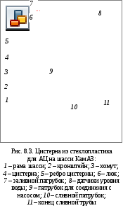 Eastern is fixed at three points. In front of the support 16
articulated, bolted to it 18
shock absorbers fixed 17
... In the back with two supports 19
through shock absorbers 20
on bars 21
the tank is installed on the frame and secured with stepladders 12
.
Eastern is fixed at three points. In front of the support 16
articulated, bolted to it 18
shock absorbers fixed 17
... In the back with two supports 19
through shock absorbers 20
on bars 21
the tank is installed on the frame and secured with stepladders 12
.
Many ACs on the chassis of ZIL, Ural, etc. are equipped with tanks of this type.
Another type of tanks is used at ATs-3-40 (4326), ATs-5-40 (4925), etc. Their basis is (Fig. 8.3) the body 4 with stiffeners 5 with rounded corners. There is a hatch at the top of the tank 6 , intended for inspection and cleaning of the internal cavity. The hatch is closed with a lid 6 to which the branch pipe is welded 7 for filling the tank with water.
There is a branch pipe at the bottom of the tank 9 to connect it to the pump, drain pipe 10 and the lower end of the drain pipe 11 .
The tank has five sensors 8 water level, which is a plastic plug with electrodes soldered into it. When the water reaches the level of the sensors, the electrical circuit is closed and the corresponding LED on the instrument panel lights up. Light guides for signaling the water level in the tank are located on the instrument panels installed in the pump compartment and the driver's cab.
Tank 4 mounted on brackets 2 attached to the chassis frame beams 1 ... The tank is fastened with clamps 3 bolted with nuts on the brackets 2 .
Foaming agent tanks are made with a capacity of 0.08 to 1 m 3, they must be at least 6% of the tank capacity. They are constructed from of stainless steel... Pipelines and fittings to them should be made of materials that are corrosion-resistant with respect to foaming agents. The design of the foam tanks should exclude the spillage of the foam concentrate from the tanks when the AC moves and when it is fed into the pump. Constructive measures or layout techniques must ensure a positive temperature of the foaming agent in the tanks.
General information about fire trucks.
Fire truck is a motorized technical means with equipment on the chassis of a car designed to prevent, limit development, extinguish a fire, rescue and protect people and property in a fire.
Fire trucks are designed for:
Delivery of combat crews, fire extinguishing equipment and fire fighting equipment to the required area of operations;
Providing the required amount of fire extinguishing agents to the combustion center;
Performing a number of special works before and during fire extinguishing.
Depending on the purpose of the equipment that are equipped with fire trucks, they are divided into:
Basic;
Special;
Auxiliary.
Basic fire trucks
Basic fire trucks - These are fire trucks designed to deliver personnel to the place of call, extinguish fires and carry out emergency rescue operations with the help of extinguishing agents and fire fighting equipment transported to them, as well as for supplying extinguishing substances from other sources to the place of fire.
The main fire trucks are classified into:
- general purpose vehicles(for extinguishing fires in cities and towns) which include tank trucks, auto pumps, pump and hose trucks, first aid vehicles, etc.;
- targeted vehicles(for extinguishing fires at specific facilities of airports, oil depots, gas fountains, etc.) these include fire-pumping pumping stations, vehicles for foam extinguishing, powder extinguishing, gas and gas-water extinguishing, combined extinguishing, airfield vehicles.
General purpose fire trucks
Fire tank truck (AC) This is a fire engine equipped with a fire pump, containers for storing liquid fire extinguishing substances and means for their supply, and is designed to deliver personnel, firefighting tools and equipment to the fire site, carry out actions to extinguish the fire and fire extinguishing systems.
Firefighting tankers are an independent tactical unit that form the basis of the firefighting fleet. fire department and used 90% of cases when leaving the units on alarm.
Regardless of the base chassis, all tank trucks have pumping units, tanks and tanks for extinguishing agents, pipeline fittings, a water intake system and a foaming agent supply system. All of these elements are connected by pipelines that form water-foam communications.
With the help of tank trucks, you can supply water to extinguish fires:
Directly from the tank;
To take and supply water from water supply networks, from artificial and natural water sources, including with the help of hydraulic elevators;
Pump water over long distances.
Depending on the carrying capacity and capacity of fire extinguishing agents, tank trucks are divided into three groups:
- lungs with a water tank capacity up to 2 cubic meters. used in small settlements;
- average with a water tank capacity of up to 4 cubic meters, they are the main type of fire trucks for most cities and large facilities;
- heavy with a water tank capacity of more than 4 cubic meters. and pumps with a capacity of 40-60 l / s. Designed primarily for individual objects and settlements with insufficiently developed water supply.
LESSON 1: Classification of the main fire trucks for general use. Purpose, modification, performance characteristics of fire and rescue vehicles in service. General information about the purpose and arrangement of parts, assemblies and groups of mechanisms of the main fire and rescue vehicles. Report card of fire fighting tool and equipment on a fire engine. Report card a
TOPIC 4: Basic general purpose fire and rescue vehicles.
LESSON 1: Classification of the main fire trucks for general use. Purpose, modification, performance characteristics of fire and rescue vehicles in service. General information about the purpose and arrangement of parts, assemblies and groups of mechanisms of the main fire and rescue vehicles. Report card of fire fighting tool and equipment on a fire engine. Report card of the rescue equipment on the rescue vehicle. Testing and maintenance of fire fighting tools and equipment.
LESSON 2: Sequence of work on fire trucks: installation on a water source; water supply from a tank truck (open reservoir, water supply network); pumping water; submission of VMP; supply of compression foam "NATISK"; water supply by a pump from a reservoir using a hydroelevator; water supply using a fire monitor. Rules for the operation of fire trucks. Safety requirements for the operation of a fire-fighting vehicle of general use.
BASIC DOCUMENTS AND LITERATURE USED IN THE DEVELOPMENT OF THE DESIGN:
Fire Trucks: A Fire Truck Driver's Textbook. - St. Petersburg, 2005;
Textbook "Fire fighting equipment";
- "On the approval of the norms of the timesheet of the PTV and ASO for the main and special fire vehicles manufactured since 2006". (Order of the Ministry of Emergency Situations of Russia dated July 24, 2006 No. 425);
1. Introductory part (10 min.)
Staff building, announcement of the topic and objectives of the lesson, a short survey on the previous topic.
2. The main part (70 min.)
General purpose fire trucks
General arrangement of fire fighting tankers
Depending on the carrying capacity of the base chassis and the volume of tanks used, fire tankers are divided into three groups:
1. Light - with a volume of tanks up to 2 m3.
2. Medium - with a volume of tanks from 2 to 4 m3.
3. Heavy - with a tank volume of more than 4 m3.
Fire-fighting tankers have a structural similarity and consist of common basic elements of units, systems and assemblies (Fig. 1, 2).
Rice. 1. Fire tanker truck: 1 - engine; 2 - chassis; 3 - driver's cab; 4 - crew cabin; 5 - tank; 6 - body compartments; 7 - body of a fire truck; 8 - pump compartment
Rice. 2. General arrangement of a fire tanker: 1 - body; 2 - tank-3 - foam concentrate tank; 4 - chassis with an engine; 5 - system remote control engine and clutch; 6 - additional cooling system; 7 - additional electrical equipment; 8 - exhaust system; 9 - additional transmission of the fire pump drive; 10 - pumping unit
Performance characteristics of firefighters and rescue vehicles in service
The performance characteristics of the AC-3,0-40 / 2 (433362)
Basic chassis ZIL-433362
Wheel formula 4 × 2
Gross weight 10000 kg Dimensions:
Height 7200 mm 2500 mm 3200 mm Motor:
Power carburetor
Maximum speed 90 km / h Water tank capacity at least 3000 liters Foaming agent tank capacity 180 liters Fire pump:
NTSPK-40 / 100-4 / 400
Rated pump flow:
At a head of 100 m.w.st.
At a head of 440 m.w.st.
When two stages work together:
High 40 l / s
Normal pressure
Sleeve length on reel
Productivity of the high-pressure spray gun 60 meters 0.2 ÷ 2 l / s
Vacuum system automatic (possibly
Manual control)
The greatest geometric suction height is not less than 7.5 meters The time of suction from a height of 7.5 is more than 30 seconds for me.
Rice. 3, 4, 5. Tank truck АЦ-3,0-40 / 2 (433362).
The performance characteristics of the AC-5.0-60 (43114) 20VR
Parameter name Indicator
Basic chassis KamAZ-43114
Gross weight 15535 kg Overall dimensions:
Height 8200 mm 2500 mm 3350 mm Motor:
The number of places of combat crew 7 people
Maximum speed 90 km / h Water tank capacity, not less than 5000 liters Foaming agent tank capacity 420 liters Fire pump:
Location centrifugal
Rated pump flow: not less than 60 l / s
Foam concentrate dosage level, adjustable
The largest number of simultaneously operating air-foam shafts of the GPS-600 type up to 7 shafts of the GPS-600 type
Vacuum system (duplicated):
2) suction gas-jet device;
Automatic vacuum system.
An autonomous heating system for the pump room is available ( heater"Planar")
There is an autonomous heating system for the crew cabin (autonomous heater "Planar")
Model of a portable fire monitor "AKRON Mercury Master 1000ТМ" (Style 1346) (QПЛС = 19.0 l / s; 31.6 l / s; 50.5 l / s; 63.3 l / s)
Rice. 6, 7, 8. Tank truck АЦ-5,0-60 (43114) 20ВР.
The performance characteristics of the AC-5.0-40 (43114) 003TV
Parameter name Indicator
Basic chassis KamAZ-43114
Wheel formula 6 × 6 (there is a function of blocking center and inter-wheel differentials)
Gross weight 15450 kg Overall dimensions:
Height 8500 mm 2500 mm 3400 mm Motor:
Power diesel, turbocharged and intercooled
The number of places of combat crew 7 people
Maximum speed 90 km / h Water tank capacity, not less than 5000 liters Foaming agent tank capacity 310 liters Fire pump:
Location centrifugal
Nominal head at the pump outlet 100 + 5 m.w.c. (10 + 0.5 kgf / cm2)
Foam concentrate dosage level, adjustable
Vacuum system suction gas jet device
The greatest geometric suction height is not less than 7.5 meters The time of suction from a height of 7.5 is more than 40 s for me.
There is an autonomous heating system for the pump compartment (autonomous heater type OV-65)
There is an autonomous heating system for the crew cabin (autonomous heater "Webasto")
Stationary fire monitor model SLS-20
Rice. 9, 10, 11 Tank truck АЦ-5,0-40 (43114) 003TV.
The performance characteristics of the AC-3,2-40 (433124)
Indicator name Value
Basic chassis ZIL-433124
Wheel formula 4 x 2
Gross weight 11610 kg Overall dimensions:
Height 7610 mm 2500 mm 3140 mm Engine:
Power carburetor, V-shaped
8-cylinder
The number of places for a combat crew of 7 people
Maximum speed 90 km / h Water tank capacity at least 3200 liters Foaming agent tank capacity 200 liters Fire pump:
Location centrifugal
Rated pump flow: not less than 40 l / s
Nominal head at the pump outlet 100 + 5 m.w.c. (10 + 0.5 at.)
Foam concentrate dosage level, adjustable
Vacuum system gas jet vacuum apparatus
Maximum geometric suction head 7 meters Suction time from a height of 7 me more than 40 s
Rice. 12 Tank truck АЦ-3,2-40 (433124)
The performance characteristics of APP-1,0-40 / 2 (5301 YO) 001ТМ
Parameter name Indicator
Basic chassis ZIL-5301YUO
Wheel formula 4 × 2
Gross weight 6950 kg Dimensions:
Height 6950 mm 2350 mm 2680 mm Engine:
Power diesel, turbocharged
The number of places of combat crew 3 people
Maximum speed 95 km / h Water tank capacity at least 1000 liters Foam concentrate tank capacity 90 liters Fire pump:
Location centrifugal two-stage combined
NTSPK-40 / 100-4 / 400
Rated pump flow:
At a head of 100 m.w.st.
At a head of 440 m.w.st.
When two stages work together: - low
High 40 l / s
Rated head at the pump outlet:
Normal pressure
High pressure not less than 100 mWC (10 kgf / cm2)
Not less than 440 mWC (44 kgf / cm2)
Foam concentrate dosage level, adjustable
High pressure hose reel:
Sleeve length on reel
Capacity of SRVD-2/300 60 meters 0.2 ÷ 2.0 l / s
Vacuum system automatic
The highest geometric suction height is not less than 7.5 meters. The time of suction from a height of 7.5 m is not more than 30 s.
Electric generator "VEPR" ADP-230VYA:
Rated voltage
Rated frequency
Maximum power 230 V
Lighting mast:
Lifting height
Hoist drive
Number / power of floodlights 4.25 m.
Pneumatic (compressed air)
2 pcs. / 1.0 kW
Electric Rescue Tool Kit:
Chainsaw "Parma"
Angle grinder (grinder type) 1 pc.
Cable reels: type
Working voltage / quantity / length portable
230 V - 1 pc. / 50 m
Rice. 13, 14, 15, 16. First aid car АПП-1,0-40 / 2 (5301ЮО) 001ТМ.
The performance characteristics of ANR-40-1500 (433112) 35VR
Parameter name Indicator
Basic chassis ZIL-433112
Wheel formula 4 × 2
Gross weight 9600 kg Dimensions:
Height 7850 mm 2500 mm 3200 mm Engine:
Carburetor power (Euro-3)
The number of places of combat crew 6 people
Maximum speed 90 km / h Capacity of the foam concentrate tank, not less than 1500 liters Number of pressure fire hoses with a diameter of 77 mm / maximum length of the main line 56 pcs. / 1120 meters Number of pressure fire hoses with a diameter of 51 mm / maximum length of the working line 12 pcs. / 240 meters Fire pump:
Location centrifugal
Average (in the cockpit of the combat crew)
Rated pump flow: not less than 40 l / s
The nominal head at the pump outlet is 100 + 5 m. Water. Art. (10 + 0.5 kgf / cm2)
Foam concentrate dosage level, adjustable
Vacuum system gas jet vacuum apparatus
The greatest geometric suction height is not less than 7.5 meters The time of suction from a height of 7.5 is more than 40 s for me.
Maximum possible extinguishing area:
Low expansion rate (0.1 ... 0.15 l / s × m2)
Medium expansion (0.05 ... 0.08 l / s × m2) with 4 SVP-4 barrels: St = 320-213 m 25 with GPS-600 barrels: St = 600-375 m21 with GPS-2000M barrel and 2 GPS-600 barrels: St = 640-400 m2 Maximum possible extinguishing volume with medium expansion foam (KZ = 3) 1 barrel GPS-2000M VT = 400 m3;
5 shafts ГПС-600 VT = 600 m3
Rice. 17, 18, 19, 20. Pump and hose truck АНР-40-1500 (433112) 35ВР.
Additional cooling system for the engine, units and assemblies of the fire tanker
When fighting fires, firefighting tankers often work for a long time in stationary mode, and the efficiency of the cooling system is significantly reduced, the engine overheats due to the lack of oncoming air flow. In order to prevent the engine from overheating in stationary operating conditions of a fire engine, it is equipped with an additional cooling system.
The design of this system for all fire tankers does not have fundamental differences(fig. 21).
Rice. 21 Schematic diagram heat exchanger operation
Hot water from the engine cooling system enters the heat exchanger, where cold water from the fire pump passes through the coil. Hot water is cooled and through the upper pipe enters the radiator for additional cooling.
In fig. 22 shows the arrangement of the heat exchanger. It consists of a lower branch pipe with a thermostat, a housing in which a coil is located, made of brass pipe and for better heat transfer, made in two spirals. Its ends are brought out through the cover and, together with the fittings, are soldered to it. The cover is fastened to the body with screws through a rubber gasket.
Rice. 22 Heat exchanger device: 1 - lower branch pipe; 2-thermostat; 3 - case; 4 - coil; 5 - cover; 6 - fitting; 7 - rubber gasket; 8 - screw
If necessary, the screws can be unscrewed and the coil together with the cover can be disconnected from the body. Pipelines are connected to the fittings, through which water from the discharge pipe of the fire pump enters the coil of the heat exchanger and returns to the suction pipe of the pump.
In fig. 23 shows a schematic diagram of the operation of the additional cooling system for the engine of a fire tanker.
Rice. 23 Schematic diagram of the operation of the additional engine cooling system
Fire pump 6 is installed on the water source and supplies water to extinguish the fire. When the engine cooling system heats up to 95 ° C and above, it is necessary to turn on the additional cooling system. For this, the valve 5 of the pipeline 4, which connects the suction cavity of the pump with the coil 11 of the heat exchanger 10, is initially opened. Then, the valve 8 of the pipeline 9, connecting the pressure cavity of the pump with the heat exchanger, is opened. Cold water from the pressure chamber of the pump through the pipeline enters the coil of the heat exchanger and, after heating, returns to the suction chamber of the pump.
Hot water from the engine cooling system enters the heat exchanger through an open thermostat, is cooled by a coil and flows through the upper pipe to the radiator 1 for additional cooling, then through the lower radiator pipe it is supplied to the water pump 2 of the engine cooling system.
Before shutting down the fire pump, the water from the additional cooling system must be removed. For this, the valve 8 is closed completely and the purge valve 7 is opened. The suction cavity of the operating fire pump creates a vacuum, which propagates through the pipes through the open valve 5. The air through the open tap 7 is sucked in, passes through the pipes and frees them from the remaining water. Then the valve and the tap are closed.
An additional cooling system ensures continuous operation of the engine for the fire pump at an ambient temperature of up to + 35 ° C. At the same time, the temperature regime in the cooling system is provided in the range from +80 to +90 ° С.
Exhaust gas evacuation system
On fire tankers, the kinetic energy of engine exhaust gases is used to draw water into the fire pump using a gas jet vacuum apparatus, and thermal energy- for heating the water tank and the pump compartment in winter time.
In fig. 24 shows a schematic diagram of an exhaust gas system.
A gas-jet vacuum apparatus is attached to the branch pipes of the exhaust pipelines. Exhaust gases constantly pass through the internal cavity of the apparatus and enter summer time through the muffler, and in winter - through the heaters of the tank and the pump room.
Rice. 24 Schematic diagram of the exhaust system:
1 - branch pipes of exhaust pipelines; 2 - gas-jet vacuum apparatus; 3 - bell with diffuser; 4 - muffler; 5, 6 - flange connections; 7 - telescopic connections; 8 - tank heater; 9 - heater of the pump compartment
Before work in the winter, a damper is installed in the flange connection 5, and the exhaust gases enter the heaters. In summer, the flange of the flange connection 5 is removed and installed in the flange connection 6.
When the gas-jet vacuum apparatus is turned on, the exhaust gases flow through the jet Vacuum pump and come out through the funnel. The created vacuum ensures that the fire pump is filled with water.
Ensuring the operation of fire rescue vehicles
The operation of the PASA, which is in the combat crew, consists of two main periods (modes): waiting and combat work when extinguishing a fire or eliminating an accident or catastrophe. Most of the time, PASA are in standby mode in full combat readiness and technically sound condition. In standby mode, the car units have a temperature equal to the air temperature in the garage. In this mode, the work is performed by the driver and personnel of combat crews for maintenance cars and fire fighting vehicles when changing the guard, as well as during the day on duty.
Daily maintenance (ETO) checks the engine, brake system, steering, pumping unit and other systems, units and assemblies. Depending on the PASA brand, it is allowed to perform a check with the engine starting.
Before driving to the place where the alarm was called, the PASA engine, after starting, runs at maximum speed in order to warm it up, as well as to fill the pneumatic drive of the brake system with air. It works especially for a long time in the presence of a base chassis equipped with a brake system with spring accumulators (KamAZ), since its design requires filling the receivers with air to a pressure of at least 4 kgf / cm2 before leaving the car.
When leaving the garage, all the main units and systems of the base chassis of the car begin to work at maximum load without preliminary warming up to optimal temperature... Most of the time, the PASA units, when proceeding to the place of call, are operated in the warm-up mode. At the same time, the engine can develop only 30-80% of the maximum power, and the transmission, its units have an extremely low efficiency due to the high value of the viscous friction of the oils used. It was found that during the forced movement of the PASA to the place of call, its average speed is 1.2-1.5 times higher than the speed of ordinary freight transport. To ensure traffic safety, PASA drivers are forced to apply braking 3-5 times more often compared to conventional vehicles. As a result, the engine, braking system, steering, chassis and other PASA units operate in a stressful mode, subject to intense wear and tear. During the operation of the PASA in countryside(when driving on uncomfortable, country roads and off-road) the units and, first of all, the engine are operated in unfavorable conditions... Engine operation in dusty conditions contributes to abrasive wear of the cylinder-piston group, crankshaft bearings and other interfaces. The steering, braking system, chassis also constantly work in a tense mode, which leads to intensive wear of parts. Therefore, more frequent adjustments, washing, cleaning and lubrication operations are required.
During combat deployment, PASA is installed, depending on its purpose, at a water source or in a combat position to perform necessary work... In some cases, it is possible to overcome off-road sections, ascents with increased road resistance when the vehicle units are operating at maximum load.
The reliable operation of the PASA in a stationary mode for the supply of fire extinguishing agents, the functioning of the ladder mechanisms, the articulated lift, the generator for powering the power tool and other mechanisms mainly depends on the technical condition of the internal combustion engine. During its long-term work it is necessary to control the temperature regime of the cooling system and the oil pressure in the lubrication system. Violation of the specified operating modes of the engine may lead to its premature failure.
On fire trucks to ensure temperature regime The engine cooling system is designed for additional cooling. In case of long-term stationary operation, in order to ensure the optimal temperature regime of the engine, a qualified application of additional cooling, constant monitoring of its operation is required.
During stationary operation of the PASA, the driver is obliged to perform maintenance operations (engine, fire pump, components and assemblies), to ensure the reliable operation of all systems to complete the assigned combat mission.
LIST OF BASIC CHECKS OF THE TECHNICAL CONDITION OF THE AC
What is checked and with what tool, instruments and equipment.
Verification method
1. Tightness of the pump and water supply
1.1. Dry vacuum test Close all valves and valves of the pumping unit. Connect an 8 m long suction line from two 125 mm diameter hoses with a plug at the end. Switch on the vacuum system. Upon reaching the maximum vacuum (the arrow of the manovacuum meter does not go down any more - it stands still) with a value of at least 0.075 MPa (0.75 kgf / cm "), close the vacuum seal and turn off the vacuum system.
A vacuum of 0.075 MPa (0.75 kgf / cm2) must be achieved in no more than 40 seconds.
The drop in vacuum should not exceed 0.013 MPa (0.13 kgf / cm ") in 150 s.
1.2. Checking the tightness by pressure The places of leakage in the connections of the pump and water-foam lines are to be identified by pressure testing with pressure (1-1.1) MPa (10-11) kgf / cm2, developed by the pump when working "on itself" with closed valves and cranes of the pumping unit. In this case, water can be taken from a tank, reservoir or hydrant.
Leaks are not allowed.
2. The time of water intake from the reservoir from the moment the vacuum system is turned on (opening the vacuum seal) until water appears in the eye of the vacuum seal at a suction height of 7-7.5 m and a suction line 8 m long.
The time should not exceed 40 s.
3. Operation of the foam mixer
Check the operation of the foam mixer by drawing water instead of the foam concentrate from an external container through a 32 mm hose with a length of 4 m at each position of the dispenser (1, 2. 3, 4, 5).
The time for emptying a test volume of 100 liters should correspond to:
OPERATING PROCEDURE
Installation of AC on fire
The AC should be kept in the garage of the fire department, as a rule, in full readiness: filled with fuel, oil, with a tank filled with water and a foaming agent - a foam tank, equipped with a PTV.
Upon arrival at the scene of the fire, depending on the presence of an open reservoir or hydrant, as well as, on the method work ahead(water supply or air-mechanical foam) AC is installed in a place that is safe in terms of exposure to fire and allows, if necessary, to quickly evacuate. At the same time, it is necessary to strive for the length of the pressure line and the number of bends of the hoses during laying to be minimal.
After making sure that you have chosen the right place, you must:
Set the AC with the idling engine to the handbrake, the gearshift roar should be in the neutral position, and the fuel control lever in the pump compartment should be in the idle position, i.e. put in the extreme position "away from you", (pump operation without water on high revs or unacceptable for a long time);
Depress the clutch pedal, turn on the PTO and smoothly release the clutch pedal (pump
Switched on);
In case of insufficient external lighting, use the switches on the switchboard to turn on the lighting in the body compartments and turn the headlights;
Lay and connect the suction and pressure lines, depending on the
From working conditions (from a tank, reservoir or hydrant);
Open the pump compartment door.
Further operations for starting the pump depend on the operating conditions.
Operation from the tank
When working from a tank, it is necessary:
Check the reliability of the installation of the plug on the suction pipe of the pump;
Open one of the pressure valves (valves) of the fire pump to release air and open the valve on the pipeline from the tank to fill the pump with water; Note. It is not recommended to open the valve of the vacuum seal to release air in order to avoid water ingress into the vacuum pump;
Open pressure valves (valves) smoothly;
Squeeze the fuel control lever in the pump compartment "towards yourself", increasing the engine speed of the car and setting the required pump operation mode.
Work from the reservoir
When working from a reservoir, you must:
Remove from the canisters and dock the suction hoses with the suction mesh, connect the suction line to the water intake pipe from the reservoir, lower the end of the suction line with the mesh into the reservoir (the mesh should be lowered at least 300 mm below the water level, but not to the bottom) ;
Turn off the pump drive by squeezing the clutch release lever "towards you" and fixing it (it is allowed not to turn off the pump drive, while the car engine must be idling);
Check the closed position of all valves and valves of the pumping unit, turn on the vacuum system (open the vacuum shutter and turn on the vacuum unit in automatic or manual mode according to the manual for the vacuum pump or the manual for the NCPK);
After filling the fire pump with water and turning off the vacuum unit (automatic or manual), close the vacuum seal, turn on the pump drive by setting the clutch release lever to its original position;
Increase engine speed and. after the pump develops required pressure, smoothly open the pressure valves (taps) of the pump and set the required operating mode of the pump.
When working with a high-pressure spray gun, open the high-pressure pressure valve and turn on the high-pressure stage in accordance with the manual at the NCPK.
Hydrant operation
When working with a hydrant, you must:
Open the cover of the hydrant well with a hook from the PTV;
Install a fire hydrant on the hydrant and connect a water collector to the suction pipe of the pump;
Connect the column to the water collector using pressure-suction hoses with a diameter of 75 mm and a length of 4 m;
Open the valves of the hydrant and the dispenser, open one of the pressure valves (valves) for air release, fill the pump with water;
Open the pressure valves (valves) smoothly, increase the engine speed and set the required operating mode of the pump.
Air-mechanical foam feeding
Foam generators are attached to the pressure hoses.
When supplying air-mechanical foam, it is necessary to maintain the pressure in the pump normal pressure within (0.7-0.8) MPa [(7-8) kgf / cm2], when this pressure is reached, it is necessary to set the directional arrow of the foam mixer to the scale division corresponding to the capacity of the attached foam generators.
To form air-mechanical foam, water can be taken into the pump from a tank, reservoir or hydrant, and the foaming agent can be taken from a foam tank or a third-party container.
Foaming agent intake from the foam tank, and water from the tank
When taking a foam concentrate from a foam tank, and water from a tank, you must first perform work in accordance with section 10.2 of this OM, while before opening the pressure valves (valves) of the pump, you must open the foam mixer tap. After opening the pressure valves (valves) of the pump, set the required operating mode and open the tap from the foam tank to the foam mixer.
Suction of foaming agent from a foam tank, and water from a reservoir or hydrant When taking a foaming agent from a foam tank, and water from a reservoir or hydrant, you must first perform the work in accordance with section 10.3 or 10.4. When taking water from the hydrant, the pressure in the suction pipe of the pump should be no more than 0.25 MPa (2.5 kgf / cm2), the pressure is regulated by a damper built into the water collector, as well as by fire hydrant valves.
Before opening the pressure valves (valves) of the pump, it is necessary to open the valve of the foam mixer. After opening the pressure valves of the pump, set the required operating mode and open the tap from the foam tank to the foam mixer.
Safety requirements for the operation of a fire-fighting vehicle of general use.
250. The technical condition of fire trucks must meet the requirements of the manufacturer's instructions. Accident-free and safe work provided by their timely and qualified service by drivers and mechanics, who are responsible for the good condition of the vehicles, specials and units assigned to them.
251. Doors of the driver's cabin and combat crew, as well as the doors of the body compartments of fire trucks should be equipped with automatically locking locks, securely held closed and fixed in open positions... Doors must be equipped with a device that gives a signal to the driver's cab instrument panel to open them. Doors that open upwards must be fixed at a height for easy and safe service.
252. Access to equipment, tools and control panels located in compartments and on platforms of fire trucks must be safe. The roofs and platforms of such vehicles must have a flooring with a surface that prevents slipping, and the height of the side railing at the roofs of the bodies is not less than 100 mm.
253. In order to constantly keep the ladders (car lifts) in good condition, by order of the head of the GPS unit, a person responsible is appointed to monitor safe operation car.
Inspection of fire trucks is carried out by the drivers assigned to them when taking up combat duty.
254. On ladders with elevators, the operability of the elevator car catchers is checked at least once a month. Inspection of lifting devices should be carried out by a person responsible for their good condition in accordance with the temporary regulations for the maintenance of these units. The results of checking the catchers of the elevator car and the inspection of auxiliary load-gripping devices are drawn up in the prescribed manner.
255. The results of the technical inspection of ladders (car lifts) are recorded in the form of the fire truck by the person who performed the inspection.
During the initial survey, this record confirms that the ladder (car lift) is in good condition and that maintenance has been carried out.
256. Drivers who have passed special training, training in safe methods of working on electrical installations, having an electrical safety admission group of at least the third and having received a certificate of the established form issued by the qualification commission of the territorial management body of the State Fire Service. Persons who have been trained in safe methods of working on electrical installations and who have an electrical safety admission group of at least the third are allowed to work on fire trucks with electric power units.
257. To work on motor pumps are allowed persons who have undergone training of fire motor pump mechanics and received a certificate of the established form.
258. The electronic protection of the electric power plant of the fire engine of the gas and smoke protection service must ensure instant disconnection (no more than 0.05 s) of the power supply in cases of breakdown of the insulation of the power tool or a decrease in its resistance.
In the event of a malfunction of the generator of the power plant or the appearance of signs indicating its failure, the switchboard of the car is connected to the external power grid. The distance from the connection point to the car must not exceed 50 m. The parameters of the pantographs must correspond to the parameters of the electrical network: voltage - 220 - 230 V, current frequency - 50 Hz.
Self-study assignment: Review the material covered by yourself.