The number of smoke detectors in the room according to the norms. Arrangement of fire detectors - problem cases
Question:
Installed a fire alarm system at the facility. Smoke detectors have been installed, incl. on an Armstrong suspended ceiling, in the center of the tiles. The fire inspector claims that this is unacceptable, contrary to SP 5.13130.2009.
Does the inspector really have grounds for such a remark, and are we obliged to fulfill his requirement to move the detectors to the intersection of the tiles?
Answer:
Requirements for automatic fire alarm installations (AUPS) are currently established:
- Federal Law No. 123-FZ of July 22, 2008 "Technical Regulations on the Requirements fire safety"(as amended on 07/13/2015);
- GOST R 53325-2012 "Fire fighting equipment. Technical means fire automatics. Are common technical requirements and test methods" (rev. 06.11.2014);
- SP 5.13130.2009 "Systems fire protection. Settings fire alarm and automatic fire extinguishers. Design norms and rules" (as amended on 06/01/2011).
In accordance with clause 13.3.4 of SP 5.13130.2009, point fire detectors should be installed under the ceiling.
If it is not possible to install the detectors directly on the ceiling, they can be installed on cables, as well as walls, columns and other load-bearing building structures.
In accordance with paragraph 13.3.16 of SP 5.13130.2009, floor-mounted detectors can be used to protect the space located below the perforated false ceiling, if the following conditions are simultaneously met:
- perforation has a periodic structure and its area exceeds 40% of the surface;
- minimum size each perforation in any section is at least 10 mm;
- the thickness of the false ceiling is no more than three times the minimum size of the perforation cell.
If at least one of these requirements is not met, the detectors must be installed on the false ceiling in the main room, and if it is necessary to protect the space behind the false ceiling, additional detectors must be installed on the main ceiling.
Accordingly, in clause 13.3.4 of SP 5.13130.2009, "other load-bearing building structures" means precisely building structures that relate to load-bearing elements buildings.
In accordance with clause 5.4.2 of SP 2.13130.2012 "Fire protection systems. Ensuring the fire resistance of protected objects" (as amended on 10/23/2013), load-bearing elements of buildings include bearing walls, columns, ties, stiffening diaphragms, trusses, elements of floors and bare roofs (beams, crossbars, slabs, floorings), if they participate in ensuring the overall stability and geometric stability of the building in case of fire.
The structures (including frames) of the Armstrong false ceiling, as well as the filling elements (including tiles) of the Armstrong false ceiling, do not belong to the load-bearing building structures of the building.
In accordance with paragraph 13.3.16 of SP 5.13130.2009, detectors can be installed on a false ceiling, but the procedure for their placement on false ceiling structures is not regulated.
In accordance with clause 13.3.18 of SP 5.13130.2009, placement and use fire detectors, the order of application of which is not defined in this set of rules, must be carried out in accordance with the recommendations agreed upon in the prescribed manner.
In accordance with clause 13.1.11 of SP 5.13130.2009, fire detectors should be used in accordance with the requirements of this set of rules, other regulatory documents on fire safety, as well as technical documentation for detectors of specific types.
In accordance with clause 4.2.7.2 of GOST R 53325-2012, the operational documentation of the IP must contain the required amount of technical data and information on installation and operation, indicating the scope and recommended frequency of maintenance.
In accordance with clause 4.2.7.3 of GOST R 53325-2012, the delivery set of the IP should ensure their installation without the use of non-standard equipment and non-standard tools. If it is necessary to use non-standard tools, they must be included in the scope of supply.
Accordingly, the installation of fire detectors on an Armstrong false ceiling is possible both on the frame of the false ceiling and on the tiles of the false ceiling, provided that the technical documentation for specific fire detectors determines the procedure for installing fire detectors in the filling elements (tiles) of the false ceiling.
Some progress is noticeable in the direction of harmonization of GOST R 53325 with European standards. Perhaps in the near future our market will get rid of puzzle manual call points, and users will no longer need to replace or “duplicate” manual call points when keys are lost.
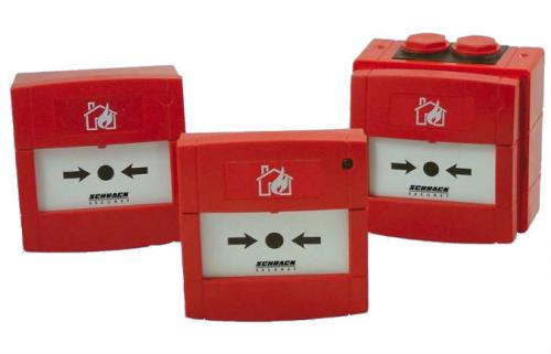
A manual fire detector (IPR), as defined by GOST R 53325-2009, is a fire detector "designed to manually turn on the signal fire alarm". The transfer of the IPR to the “Fire” mode is carried out by acting on the so-called drive element, which at the present time, according to GOST R 53325, can literally use anything: a lever, a button, a fragile element or other device.
"Duplication" of manual call points
Probably, the low reliability of contact switches, the possibility of contact oxidation, loss of spring properties, etc. were taken into account when developing the first IPR designs. As a result, IPR began to be produced with a lever drive element with a magnet and a reed switch. The reed switch is a hermetically sealed switch with a spring contact made of magnetic material. magnetic field the contacts of the reed switch were closed. When the IPR was activated, the lever was moved to a horizontal position, the magnet moved away from the reed switch, and its contacts opened. Returning to the standby mode of the IPR is possible only with the use of a special key, which is often lost during long-term maintenance.
Rice. 1 "Duplicate" IPR
As a result, you can observe the following picture: two manual call points located in one place, one IPR in the “Fire” mode, the other in standby mode To prevent the key from the new IPR from being lost, it was “hidden” under a protective transparent cover (Fig. 1 ).
Puzzle detectors
Obviously, the variety of ways to activate the IPR only reduces the level of fire safety. In our market there are real puzzles with levers, brackets, straps in cases of various shapes. It is not possible to quickly determine what this device is intended for and how to handle it.
"Understandable" manual call points
The European standard EN 54-11 sets clear requirements for the shape and dimensions of the housing and drive element, as well as the shape and dimensions of the symbols. This determines the absence of exotic designs among imported handbrakes and the ease of handling them.
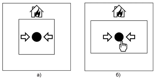
Rice. 2. The front panel of the handbrake according to EN 54 - 11
According to EN 54-11, only square housings with face sizes from 85x85 to 1 35x1 35 mm can be used and only with a flat drive element - square or rectangular. The square drive element is 25% of the area of the front panel, and the rectangular drive element is 32% of the area with an aspect ratio of 1:2 (Fig. 2 a, b).
Harmonization of GOST and European standards
Some progress can be noted in the direction of harmonization of our GOST R 53325 with severostandards. Yes, in the project new version are present in the form of recommendations examples of IPM designs and symbols used, their location and sizes from the SO 7240 standard. In the requirements for the design of IPM, in addition to square cases with drive elements of square and rectangular shape, there is an example of the appearance of an IPR with a round body and a round drive element.
The eurosymbols that should be applied to the front surface of the IPR are given, and it is also indicated in which place they should be applied. For example, the symbol "House" should be located above the drive element on the central axis of the front surface of the IPR. In the area where the drive element is located, the symbol "Arrows" should be applied. Defined not only appearance each character, but also their relative sizes.
In addition, with the introduction of a new version of GOST R 35525 in the near future, manual call points will be classified as in European standards - in two classes, depending on the number of actions required to activate the IPR. If it is enough to perform one action to transfer class A IPR to the “Fire” mode, then class B IPRs are activated after performing two actions. The first impact on a flat element is the same in terms of force in the IPR of both classes, but in the IPR of class B, then another, for example, pressing a button is performed. On the drive element of the IPR class B, the symbol "Hand" is additionally applied (Fig. 2.6). For IPR class A, a transparent cover is allowed to protect the drive element from accidental impact. Perhaps, in future versions of the rules, the appointment of IPR of class A and class B will be determined.
Installation rules
The set of rules SP 5.13130.2009 determines the installation of manual fire detectors on walls and structures at a height of (1.5 ± 0.1) m from the ground or floor level to the control (lever, button, etc.); at a distance of at least 0.75 m from other controls and objects that prevent free access to the detector; at a distance of no more than 50 m from each other inside buildings and no more than 150 m from each other outside buildings.
In accordance with the recommendations given in Appendix H to SP 5.13130.2009, in industrial buildings, IPR should be installed at the exits from workshops, warehouses, etc., along escape routes, in the corridors, as well as on the landings of each floor, in cable structures at the entrance to the tunnel, at emergency exits from the tunnel and at the branchings of the tunnels In the administrative and amenity and public buildings IPR are installed in corridors, halls, lobbies, on landings and at exits from the building. Illumination at the installation site of a manual fire detector must be at least standard for these types of premises.
12. Fire alarm systems
General provisions when choosing the types of fire detectors for the protected object
12.1. The choice of the type of point smoke detector is recommended to be made in accordance with its ability to detect various types of smoke, which can be determined according to GOST R 50898.
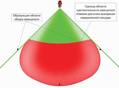
12.2. Fire flame detectors should be used if an open flame is expected to appear in the control zone in the event of a fire at its initial stage.
12.3. The spectral sensitivity of the flame detector must correspond to the emission spectrum of the flame of combustible materials located in the control zone of the detector.
12.4. Thermal fire detectors should be used if significant heat release is expected in the control zone in the event of a fire at its initial stage.
12.5. Differential and maximum-differential thermal fire detectors should be used to detect a fire source, if there are no temperature drops in the control zone that are not associated with the occurrence of a fire that can cause the operation of these types of fire detectors.
Maximum thermal fire detectorsNot recommended for indoor use
with low temperatures (below 0 o C);
with the storage of material and cultural values.
Note.Except in cases where the use of other detectors is impossible or impractical.
12.6. When choosing thermal fire detectors, it should be taken into account that the response temperature of maximum and maximum differential detectors must be at least 20° C above the maximum allowable room temperature.
12.7. Gas fire detectors are recommended to be used if in the control zone in the event of a fire at its initial stage, the release of a certain type of gases in concentrations that can cause the detectors to operate is expected. Gas fire detectors should not be used in rooms where, in the absence of a fire, gases may appear in concentrations that cause the detectors to operate.
12.8. In the event that the dominant fire factor is not determined in the control zone, it is recommended to use a combination of fire detectors that respond to various fire factors, or combined fire detectors.
12.9. The choice of types of fire detectors, depending on the purpose of the protected premises and the type of combustible load, is recommended to be made in accordance with Appendix 12.
12.10. Fire detectors should be used in accordance with the requirements state standards, fire regulationssecurity,technicaldocumentation and taking into account climatic, mechanical, electromagnetic and other influences at their locations.
12.11. Fire detectors designed to issue notifications forAUP control, smoke removal, fire warning, shouldbe resistant to electromagnetic interferencewith a degree of rigidity not lower than the second according to NPB 57-97.
12.12. Smoke detectors powered by a fire alarm loop and having a built-in sound annunciator are recommended to be used for prompt, local warning and determining the location of a fire in rooms in which following conditions:
The main factor in the occurrence of a fire in the initial stage is the appearance of smoke;
Presence of people is possible in the protected premises.
Such detectors must be included in single system fire alarm with the output of alarm notices to the fire control panel located in the premises of the personnel on duty.
Notes:
1. These detectors are recommended for use in hotels, in medical institutions, in the exhibition halls of museums, in art galleries, in the reading rooms of libraries, in trade premises, in computer centers.
2.Applicationof these detectors does not exclude the equipment of the building with a warning system in accordance with NPB 104.
Requirements for the organization of fire alarm control zones
12.13. It is allowed to equip a control zone with one fire alarm loop with fire detectors that do not have an address, including:
premises located on different floors, with a total area of 300 m 2 or less;
up to ten isolated and adjacent premises, with a total area of not more than 1600 m 2 located on the same floor of the building, while isolated rooms must have access to a common corridor, hall, lobby, etc.;
up to twenty isolated and adjacent rooms, with a total area of not more than 1600 m 2 located on the same floor of the building, while isolated rooms must have access to a common corridor, hall, lobby, etc., if there is a remote light alarm about the operation of fire detectors above the entrance to each controlled room.
12.14. The maximum number and area of premises protected by one ring or radial loop with addressablefire detectors, is determined by the technical capabilities of the receiving and control equipment, the technical characteristics of the detectors included in the loop and does not depend on the location of the premises in the building.
Placement of fire detectors
12.15. The number of automatic fire detectors is determined by the need to detect fires over the entire controlled area of premises (zones), and for flame detectors - and equipment.
12.16. At least two fire detectors should be installed in each protected room.
12.17. It is allowed to install onefire detector if the following conditions are met simultaneously:
a) the area of the room is not more than the area protected by the fire detector, specified in the technical documentation for it, and not more than the average area specified in tables 5, 8;
b) automatic monitoring of the fire detector performance is provided, confirming the performance of its functions with the issuance of a malfunction notice to the control panel;
c) identification of a faulty detector by a control panel is provided;
d) a signal from a fire detector does not generate a signal to start the control equipment that turns on automatic fire extinguishing or smoke removal systems or type 5 fire warning systems according to NPB 104.
12.18. Point fire detectors, except for flame detectors, should be installed, as a rule, under the ceiling. If it is impossible to install detectors directly under the ceiling, they can be installed on walls, columns and other load-bearing building structures, as well as mounted on cables.
When installing point fire detectors under the ceiling, they should be placed at a distance of at least 0.1 m from the walls.
When installing point fire detectors on walls, special fittings or fastening on cables, they should be placed at a distance of at least 0.1 m from the walls and at a distance of 0.1 to 0.3 m from the ceiling, including the dimensions of the detector.
When the detectors are suspended on a cable, their stable position and orientation in space must be ensured.
12.19. Placement of point heat and smoke fire detectors should be carried out taking into account the air flows in the protected room caused by supply or exhaust ventilation, while the distance from the detector to the ventilation opening should be at least 1 m.
12.20. Point smoke and heat fire detectors should be installed in each section of the ceiling with a width of 0.75 m or more, limited by building structures (beams, girders, plate ribs, etc.) protruding from the ceiling at a distance of more than 0.4 m.
If building structures protrude from the ceiling at a distance of more than 0.4 m, and the compartments they form are less than 0.75 m wide, the area controlled by fire detectors, indicated in tables 5, 8, is reduced by 40%.
If there are protruding parts on the ceiling from 0.08 to 0.4 m, the area controlled by fire detectors, indicated in tables 5, 8, is reduced by 25%.
If there are boxes in the controlled room, technological platforms with a width of 0.75 m or more, having a solid structure, spaced along the lower mark from the ceiling at a distance of more than 0.4 m and at least 1.3 m from the floor plane, it is necessary to additionally install under them fire detectors.
12.21. Point smoke and heat fire detectors should be installed in each compartment of the room formed by stacks of materials, racks, equipment and building structures, the upper edges of which are 0.6 m or less from the ceiling.
12.22. When installing point smoke detectors in rooms with a width of less than 3 m or under a raised floor or above a false ceiling and in other spaces with a height of less than 1.7 m, the distance between the detectors indicated in Table 5 can be increased by 1.5 times.
12.23. Fire detectors installed under the raised floor, above the false ceiling, must be addressable, or connected to independent fire alarm loops, and it must be possible to determine their location.The design of the raised floor and false ceiling slabs should provide access to fire detectors for their maintenance.
12.24. Fire detectors should be installed in accordance with the requirements of the technical documentation for this detector.
12.25. In places where there is a danger of mechanical damage to the detector, a protective structure must be provided that does not impair its performance and the effectiveness of fire detection.
12.26. If different types of fire detectors are installed in one control zone,their placement is made in accordance with the requirements of these standards for each type of detector.
In the case of using combined (heat-smoke) fire detectors, they should be installed according to table 8.
12.27. For rooms in which, in accordance with Appendix 12, it is possible to use both smoke and heatfire detectors, their combined use is allowed. In this case, the placement of the detectors is made according to table 8.
Point smoke detectors
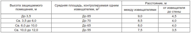
12.28. The area controlled by one point smoke detector, as well as the maximum distance between the detectors and the detector and the wall, except for the cases specified in clause 12.20, must be determined according to table 5, but not exceeding the values \u200b\u200bspecified in specifications and passports for detectors.
Table 5
|
Average area controlled one detector, m 2 |
Maximum distance, m |
||
|
between detectors |
from the detector to the wall |
||
|
Up to 3.5 |
Up to 85 |
9,0 |
4,5 |
|
Over 3.5 to 6.0 |
Up to 70 |
8,5 |
4,0 |
|
Over 6.0 to 10.0 |
Up to 65 |
8,0 |
4,0 |
|
St. 10.5 to 12.0 |
Up to 55 |
7,5 |
3,5 |
Linear smoke detectors
12.29. Emitter and receiverlinear smoke detectorshould be installed on walls, partitions, columns and other structures in such a way that their optical axis passes at a distance of at least 0.1 m from the floor level.
12.30. Emitter and receiverof a linear smoke detector should be placed on the building structures of the room in such a way that various objects do not fall into the detection zone of the fire detector during its operation. The distance between the emitter and the receiver is determined by the technical characteristics of the fire detector.
12.31. When monitoring the protected area with two or more linear smoke detectors, the maximum distance between their parallel optical axes, the optical axis and the wall, depending on the installation height of the fire detector units, should be determined from the table6.
Table 6
|
Maximum distance between optical axes of detectors, m |
Maximum distance from the optical axis of the detector to the wall, m |
|
|
Up to 3.5 |
9,0 |
4,5 |
|
Over 3.5 to 6.0 |
8,5 |
4,0 |
|
Over 6.0 to 10.0 |
8,0 |
4,0 |
|
St. 10, 0 to 12.0 |
7,5 |
3,5 |
12.32. In rooms with a height of over 12 and up to 18 m, detectors should, as a rule, be installed in two tiers, in accordance with Table 7, while:
the first tier of detectors should be located at a distance of 1.5-2 m from the upper level of the fire load, but not less than 4 m from the floor plane;
the second tier of detectors should be located at a distance of no more than 0.4 m from the floor level.
12.33. The detectors should be installed in such a way that the minimum distance from its optical axis to walls and surrounding objects is at least 0.5 m.
Table 7
|
Height of the protected premises, m |
Tier |
Detector installation height, m |
Maximum distance, m |
|
|
Between optical axes LDPI |
from the optical axis of the LDPI to the wall |
|||
|
St. 12.0 up to 18.0 |
1 |
1.5-2 from the fire load level, at least 4 from the floor plane |
7,5 |
3,5 |
|
2 |
Not more than 0.4 of coverage |
7,5 |
3,5 |
|
Point thermal fire detectors
12.34. The area controlled by one point thermal fire detector, as well as the maximum distance between the detectors and the detector and the wall, except as specified in clause 12.30,
It is necessary to determine according to table 8, but not exceeding the values specified in the technical specifications and passports for the detectors.
Table 8
|
Height Protected premises, m |
Average area controlled by one detector, m 2 |
Maximum distance, m |
|
|
between detectors |
from the detector to the wall |
||
|
Up to 3.5 |
up to 25 |
5,0 |
2,5 |
|
Over 3.5 to 6.0 |
up to 20 |
4,5 |
2,0 |
|
St. 6.0 to 9.0 |
Up to 15 |
4,0 |
2,0 |
12.35. Point thermal fire detectors should be located at a distance of at least 500 mm from heat-emitting lamps.
Linear thermal fire detectors
12.36. Linear thermal fire detectors (thermal cable) should, as a rule, be laid in direct contact with the fire load.
12.37. Linear thermal fire detectors may be installed under the ceiling above the fire load, in accordance with Table 8, while the values \u200b\u200bof the values \u200b\u200bspecified in the table should not exceed the corresponding values \u200b\u200bspecified in the manufacturer's technical documentation.
The distance from the detector to the ceiling must be at least 15mm.
When storing materials on a rack, it is allowed to lay detectors along the top of tiers and racks.
Flame detectors
12.38. Flame fire detectors should be installed on ceilings, walls and other building structures of buildings and structures, as well as on process equipment.
The placement of flame detectors must be carried out taking into accountelimination of possible effects of optical interference.
12.39. Each point of the protected surface must be monitored by at least two flame detectors, and the location of the detectors must ensure control of the protected surface, as a rule, from opposite directions.
12.40. The area of the room or equipment controlled by the flame detector should be determined based on the valueviewing angle of the detector and in accordance with its classaccording to NPB72-98 (maximum detection range of a combustible material flame) specified in the technical documentation.
Manual fire call points
12.41. Manual fire detectors should be installed on walls and structures at a height of 1.5 m from the ground or floor level.
The installation locations of manual fire detectors are given in Appendix 13.
12.42. Manual fire detectors should be installed in places remote from electromagnets, permanent magnets, and other devices, the impact of which can cause spontaneous operation of a manual fire detector.(the requirement applies to manual fire detectors, the operation of which occurs when switching a magnetically controlled contact) at a distance of:
no more than 50 m from each other inside buildings;
no more than 150 m from each other outside buildings;
not less than 0.75mBefore the detector, there should be no various controls and objects that prevent access to the detector.
12.43. Illumination at the installation site of the manual fire detector must be at least 50 lux.
Gas fire detectors.
12.44. Gas fire detectors should be installed indoors on the ceiling, walls and other building structures of buildings and structures in accordance with the operating instructions for these detectors and the recommendations of specialized organizations.
Fire control devices, fire control devices. Equipment and its placement
12.45. Control and reception devices, control devices and other equipment should be used in accordance with the requirements of state standards, fire safety standards, technical documentationand taking into account climatic, mechanical, electromagneticand other impacts at their locations.
12.46. Devices, on the signal from which the automatic fire extinguishing or smoke removal installation or fire warning is started, must be resistant to external interference with a degree of rigidity not lower than the second according to NPB 57.
12.47. Reserve capacity of control panels (number of loops) designed to work with non-address fire detectors used in conjunction with automatic settings fire extinguishing, must be at least 10% with the number of loops 10 or more.
12.48. Reception and control devices, as a rule, should be installed in a room with round-the-clock stay of duty personnel. In justified cases, it is allowed to install these devices in premises without personnel on round-the-clock duty, while ensuring separate transmission of fire and malfunction notifications to a room with personnel on round-the-clock duty, and ensuring control of the notification transmission channels. In this case, the room where the devices are installed must be equipped with a security and fire alarm and protected from unauthorized access.
12.49. Control and reception devices and control devicesshould be installed on walls, partitions and structures made of non-combustible materials. Installation of the specified equipment is allowed on structures made of combustible materials, provided that these structures are protected.steelsheet with a thickness of at least 1 mm or other non-combustible sheet material with a thickness of at least 10 mm. Wherein sheet material must protrude beyond the contour of the installed equipment by at least 100 mm.
12.50. The distance from the upper edge of the control panel and control device to the overlap alongroom made of combustible materials must be at least 1m.
12.51. When several control panels and control devices are adjacent, the distance between them must be at least 50 mm.
12.52. Control and reception devices and control devices should be placed in such a way that the height from the floor level to the operational controls of the specified equipment is 0.8-1.5 m.
12.53. The premises of the fire post or the premises with the personnel on duty around the clock should be located, as a rule, on the first or in the basement floor of the building. It is allowed to place the specified room above the first floor, while the exit from it must be in the lobby or corridor adjacent to the stairwell, which has direct access to the outside of the building.
12.54. Distancefromdoors of the fire station room or the room with personnel on duty around the clock, up tostaircase leading outside should notexceed, as a rule, 25 m.
12.55. Fire post room or room with personnel leading24-hour duty must have the following characteristics:
area, usually not less than 15 m 2 ;
air temperature within 18-25 °Сat relative humidity not more than 80%;
availability of natural and artificial lighting, as well as emergency lighting, which must comply with SNiP 23.05-95;
room lighting:
in natural light - at least 100 lux;
from fluorescent lamps - at least 150 lux;
from incandescent lamps - at least 100 lux;
with emergency lighting - at least 50 lux;
the presence of natural or artificial ventilation in accordance with SNiP 2.04.05-91;
telephone connection with fire department object or locality.
backup batteries other than sealed ones should not be installed.
12.56. In the premises of the personnel on duty, conducting round-the-clock duty, emergency lighting should turn on automatically when the main lighting is turned off.
Fire alarm lines. Connecting and supply lines for fire alarm systems and control equipment
12.57. The choice of wires and cables, the methods of their laying for organizing fire alarm loops and connecting lines must be made in accordance with the requirements of the PUE, SNiP 3.05.06-85, VSN 116-87, the requirements of this section and the technical documentation for devices and equipment of the fire alarm system.
12.58. Fire alarm loops must be carried out with the condition of ensuring their automatic integrity control along their entire length.
12.59. Fire alarm loops should be made with independent wires and cables with copper conductors.
Fire alarm loops, as a rule, should be carried out with communication wires, if the technical documentation for fire control devices does not provide for the use of special types of wires or cables.
12.60. Fire alarm loops of the radial type, as a rule, should be connected to the devices of the receiving and control firefighters through junction boxes, crosses.
In cases where the fire alarm system is not designed to control automatic fire extinguishing installations, warning systems, smoke removal systems and other engineering systems fire safety of an object, for connecting fire alarm loops of a radial type with a voltage of up to 60 V to control panels, connecting lines made by telephone cables with copper conductors of an integrated communication network of an object can be used, provided that communication channels are allocated. At the same time, dedicated free pairs from the cross-connect to junction boxes used in the installation of fire alarm loops, as a rule, should be located in groups within each junction box and marked with red paint.
In other cases, connecting lines for connecting fire alarm loops of a radial type to fire control devices should be made according to12.58.
12.61. Connecting lines made with telephone and control cables must have a reserve stock of cable cores and terminals of junction boxes of at least 10% each.
12.62. When installing a fire alarm system with fire alarm control and receiving devices with an information capacity of up to 20 loops, it is allowed to connect radial fire alarm loops directly to fire alarm control and control devices.
12.63. Ring-type fire alarm loops should be made with independent wires and communication cables, while the beginning and end of the ring loop must be connected to the corresponding terminals of the fire control panel.
12.64. The diameter of the copper conductors of wires and cables must bedetermined based on the allowable voltage drop, but not less than0.5 mm.
12.65. Power supply lines for control panels and fire control devices, as well as connecting lines for controlling automatic fire extinguishing installations,smoke extraction or warningshould be done with separate wires and cables. It is not allowed to lay them in transit through explosive and fire hazardous premises (zones). In justified cases, it is allowed to lay these lines through fire hazardous premises (zones) in the voids of building structuresclass KO or fire-resistant wires and cablesmore cables and wires laid in steel pipes according to GOST 3262.
12.66. It is not allowed to jointly lay fire alarm loops and connecting lines, control lines for automatic fire extinguishing and warning installations with a voltage of up to 60 V with lines with a voltage of 110 V or more in one box, pipe, bundle, closed channel of a building structure or on one tray.
Joint laying of these lines is allowed in different compartments of boxes and trays with continuous longitudinal partitions with a fire resistance limit of 0.25 hours from non-combustible material.
12.67. With parallel open laying, the distance from wires and fire alarm cables with voltage up to 60 V to power and lighting cables must be at least 0.5 m.
It is allowed to lay these wires and cables at a distance of less than 0.5 m from power and lighting cables, provided that they are shielded from electromagnetic interference.
It is allowed to reduce the distance to 0.25 m from wires and cables of fire alarm loops and connecting lines without interference protection to single lighting wires and control cables.
12.68. In rooms where electromagnetic fields and pickups exceed the level established GOST 23511, fire alarm loops and connecting lines must be protected from interference.
12.69. If it is necessary to protect fire alarm loops and connecting lines from electromagnetic interference, shielded or unshielded wires and cables should be used, laid in metal pipes, boxes, etc. In this case, the shielding elements must be grounded.
12.70. Outdoor wiring for fire alarm systems should generally be laid in the ground or in a sewer.
If it is impossible to lay in this way, it is allowed to lay them along the outer walls of buildings and structures, under sheds, on cables or on supports between buildings outside streets and roads in accordance with the requirements of the PUE.
12.71. mainand reserve cable lines for power supply of fire alarm systems should be laid along different routes, excluding the possibility of their simultaneous failure in case of fire at the controlled object. The laying of such lines, as a rule, should be carried out on different cable structures.
Parallel laying of the indicated lines along the walls of the premises is allowed with a distance between themin the light of at least 1 m.
Joint laying of the indicated cable lines is allowed, provided that at least one of them is laid in a box (pipe) made of non-combustible materials with a fire resistance limit of 0.75 h.
12.72. It is advisable to divide fire alarm loops into sections by means of junction boxes.
At the end of the loop, it is recommended to provide a device that provides visual control of its on state (for example, a device with a flashing signal other than red with a flashing frequency of 0.1-0.3 Hz.),as well as a junction box or other switching device for connecting equipment for assessing the condition of the fire alarm system, which must be installed at an accessible location and height.The reliability and performance of a fire extinguishing system largely depends on the correct installation, compliance with the rules and requirements for systems. One of the prerequisites is the installation standards for fire detectors, which depend on the type of devices and the characteristics of the protected area.
Calculating the distance between individual detectors and determining the place for their installation is a laborious and responsible issue that designers have to solve from scratch at each facility.

Code of Practice Governing the Installation of Fire Detectors
To guide and control the issue of installation fire fighting equipment use various regulations that define the types of detectors, requirements for them and standard indicators that the distance between fire detectors must comply with.
Main normative document in this area are NPB 88-2001, approved by order of the GUGPS on 04.06.01, which determine the norms and rules for the design of fire extinguishing installations and signaling devices.
It is also necessary to take into account the Code of Rules 5.12.130.2009 dated 03.25.09, dedicated to the norms and rules of installation automatic systems fire extinguishing, subject to subsequent changes, in which the rules for the installation of fire alarm sensors are set out taking into account the features various ceilings.
All applicable regulations and requirements are aimed at ensuring high level fire safety and the most efficient use of fire fighting equipment.
The disadvantage of these documents is their theoretical nature, i.e. they contain only a list of requirements. For practical use, various European standards are often used, which describe the nature of the ongoing combustion and fire extinguishing processes in terms of their physical nature. Thus, the standard from the UK BS 5839 allows you to simulate different stages of a fire and choose a solution for each specific situation.
Rules for placing smoke devices
There are several various types smoke detectors which are installed in various premises, and for which special rules apply for measuring the distance between them or from the wall to the detector.
- Optical point smoke devices are used in small format objects, such as residential apartments and houses, hospital premises, hotel rooms.
- Linear fire alarm systems are intended for spacious facilities such as warehouses, halls and halls. public spaces, terminals of airports or train stations.
- aspiration detectors are installed in rooms cluttered with documents and materials, for example, in libraries, museum storerooms, archives.
For reliable operation of point and aspiration devices, a fixed fixation under the ceilings is necessary, i.e. where the potential for vibration is minimal.
The coverage area of one detector depends on the height of the ceilings:
- up to 3.5 meters - 85 m 2;
- from 3.5 to 12 meters - 55 m 2;
- over 12 meters - two-level placement is required (on walls and ceiling) and the simultaneous use of point and line models.

The distance between fire alarm devices should not exceed 9 meters.
Linear devices are placed on the walls opposite each other at a distance of 9 meters. For high rooms (from 12 to 18 meters), two rows of sensors are used and a minimum distance between levels of at least 2 meters, while the lower row is located above 4 meters from the floor level, and the upper one is no closer than 40 cm from the ceiling.
At suspended ceilings smoke detectors are installed between two ceilings and directed to the exits from the ventilation.
Installation of flame detectors
The main requirement affecting the placement of fire flame detectors is the obligatory optical accessibility of the territory, i.e. the absence of barriers that prevent the fixation of the resulting flame.
Devices are mounted indoors and on open space, they can be installed on the ceiling, wall or equipment. For installation, the distance is not measured between fire detectors, but from the device to the corners. This indicator has limited limits:
- 10 cm for ceiling mounts
- 30 cm for wall fixtures.
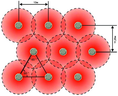
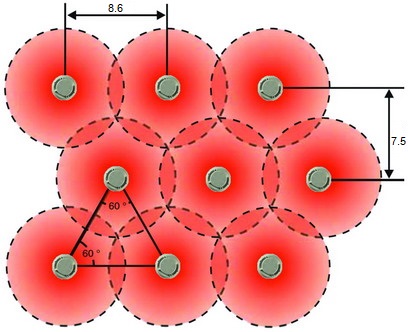
Also, the placement of sensors from each other in a rectangular room is recommended to be set according to the following parameters:
Placement of thermal linear detectors
Thermal linear detectors react to fluctuations temperature regime. They are made in the form of a thermal cable, receptive along the entire length. The distance between fire alarm sensors inside buildings is 10-12 meters. For installation outside buildings (under awnings), the installation regulations require that a distance of at least 50 cm from the awning to the cable be maintained.
Thermal appliances are used in rooms with a large area and high ceilings, for example, in stadiums, inside warehouses, production workshops.
The main requirement is a reliable fixation to the wall, ceiling or a good stretch without fastening, so that the fire nets are not at risk of damage. All laid cables are connected at the location checkpoint, where all information about the fire threat is submitted.
Placement of handheld devices
Manual sensors are activated directly by a person, so the placement of fire detectors is determined by the convenience of access to them.
They are installed on the walls in the room at a height of about one and a half meters from the floor, i.e. inaccessible to accidental activation by animals or children, and at the level of vision of most people.
Installation requirements are no furniture or equipment blocking access to handheld devices. Places for installing sensors should be publicly accessible and not have individual locks - stairs, corridors, halls. The distance between mounting points should not exceed 50 meters, and if external territories are controlled, then 150 meters.
"Note!
It also takes into account the distance to the lamp and its power, which affects the level of illumination of control points.
Arrangement of gas detectors
When using a fire detector, the main indicator is the physical characteristics of the gas and the room itself, i.e. probable directions and velocity of gas propagation are taken into account. Usually gas appliances are placed directly next to gas appliances with toxic or flammable gaseous substances from which leakage is possible. Objects where they decide to install gas fire detectors are industrial premises or special gas distribution points.
Placement of autonomous detectors
A feature that an autonomous fire detector has is self-activation, which does not require the presence or control of a person. Place of use - residential premises, hotel rooms, sanatoriums, rest houses and so on.
The standards for the area that falls under the control of the device is 30 square meters, and if the space or plane of the ceiling has a complex geometry, then this indicator must be reduced by a quarter, i.e. up to 23-25 meters. Taking into account the characteristics of typical protected objects, devices can be installed one per unit area.
For reliable operation of the equipment avoid direct exposure to the sun, as well as closed corners, with unreliable ventilation.
The rules provide for ceiling installation, and if it is not possible, the installation standards for wall fire detectors provide for a distance from the ceiling in the range of 10 to 30 cm.
Installation of light, sound and voice alarms
In addition to detectors that transmit information to control panels, various annunciators are widely used, i.e. devices that provide alarms and information about a fire to all people in the danger zone. The main task of this equipment is to notify people about the need for evacuation when sensors detect fires (smoke, flame, thermal level jump).
The sirens transmit signals using:
- light indication,
- voice (speech) notifications,
- sound signals(sirens, calls).
Each type has its own requirements.
Light indicators require a place accessible for viewing, and a maximum distance of 60 meters between the nearest scoreboards.
Sound and speech devices can be both indoors and outdoors, and are located at a height of about 2 meters from the floor.
Distance between alarm loops
Fire alarm loops are designed to transmit signals from the location of the sensor to the control point or the location of the siren.
Requirements for the installation of loops - the ability to bring information to the end point. Those. they must be protected from open flames or high temperatures.
Restriction in installation - distance to electrical cables not less than 50 cm, and in exceptional cases - 30 cm is allowed. This requirement is due to the following reasons:
- prevention of accidental operation fire system;
- protection against damage when the electrical network is closed.
The installation standards for fire detectors are mandatory for application. They ensure maximum efficiency of equipment operation and creation of conditions for fire safety.
One of the main components of the automatic fire alarm system (APS) are fire detectors ( firefighters sensors), which serve as sensors for early detection of a fire source in a protected room. Since the initial stage of ignition can be different (smoke, elevated temperature, open flame or something similar) and depends only on the products of combustion, then fire detectors were divided into several types, each of which is most effective in terms of exposure to a certain sign of combustion at the initial stage of a fire. Thus, six main types of fire detectors are distinguished:
- smoke detectors;
- heat detectors;
- flame detectors (light);
- gas detectors;
- combined detectors;
- manual call points.
Also, the detectors are divided according to the way of eating:
- autonomous;
- with separate power supply;
- powered by signal line;
according to the principle of reaction to the source of ignition:
- active;
- passive;
where possible to determine the location of the fire:
- targeted;
- unaddressed (threshold).
by type of controlled area:
- point;
- linear;
- voluminous.
Based on this, it becomes clear that each detector is a separate device that has its own characteristics, construction structure, principle of operation and installation requirements. All this should be taken into account when choosing fire detectors, since their characteristics and correct installation will directly affect the protection efficiency of your facility.
Requirements for the installation of fire detectors
According to the current legislation, namely set of rules SP 5.13130.2009, The placement, number and type of fire detectors in a controlled room is strictly regulated and must meet the following requirements:
1. the required number of fire detectors is determined by the area of the controlled premises;
2. in each room of the protected object, at least two fire detectors must be located, which are included in the system circuit according to the logical "OR" circuit;
3. It is allowed to install one fire detector in one room if the following conditions are met simultaneously:
The area of the controlled premises does not exceed the passport value of the controlled area of the selected detector;
The control panel (PPK) controls the health of the detector;
The detector has a light indication of a malfunction, and the duty personnel can replace it within the lines established by the regulations;
The fire alarm system does not issue a control signal fire automatics(starting fire extinguishing, notification, smoke removal) and the object does not use the 4th or 5th type of notification;
4. point fire detectors should be installed under the ceiling, so that no structures prevent the natural ingress of smoke or other combustion product onto its sensitive elements;
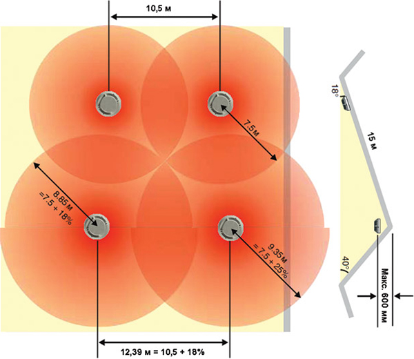
5. if the overlap of the monitored room has a slope of more than 10°, then the distance between the detectors can be increased by 20%, but other requirements must be observed SP 5.13130.2009;
6. point smoke detectors should be installed at a distance of at least 1 m from the ventilation openings so that air flows do not interfere with the natural spread of smoke;
7. If there are linear beams on the ceiling of the protected premises, the installation of smoke fire detectors should be carried out strictly adhering to the requirements of the following table:
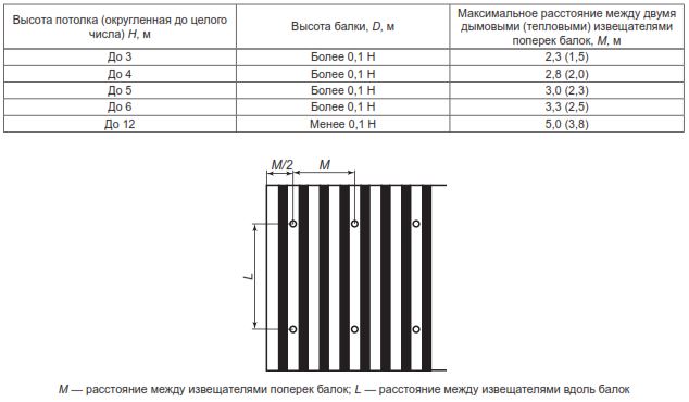
8. If there are honeycomb-shaped beams on the ceiling of the protected room, the installation of smoke fire detectors should be carried out strictly adhering to the requirements of the following table:

9. when installing point, linear or aspiration detectors in warehouses with racks, the height of which reaches less than 0.6 m before overlapping, detectors are installed in each compartment formed by racks or stored materials;
10. when installing fire detectors in rooms with a width of less than 3 m (corridors) or a height of less than 1.7 m, the distance between them may be increased by 1.5 times the nominal one;
 11. when installing fire detectors in spaces with limited access (raised floor, false ceiling, etc.), the optical identification of their operation must be brought out, while it is necessary to provide free access for their maintenance (technical hatch or something similar) ;
12. installation of any fire detector should be carried out in compliance with its technical documentation and in accordance with the requirements SP 5.13130.2009 on the given type detector;
13. when installing detectors in places where there is a risk of damage, they must be equipped with protection that will not interfere with the natural detection of the ignition factor;
14. in the case when it is not possible to accurately determine the dominant factor in the start of a fire in a room, combined fire detectors should be used or several detectors with different actions should be installed, while the installation is carried out in accordance with the requirements SP 5.13130.2009 for each detector separately;
15. if there is a perforated false ceiling in the controlled room, where the perforation occupies at least 40% of its area, the size of the perforation is not less than 10 mm, and its thickness is not more than three times the cell size, it is allowed to install detectors to control the room behind the false ceiling;
16. installation of fire detectors should be carried out so that their light indicators are directed towards the exit from the premises;
17. It is allowed to install special flowing fire detectors, which must control the ventilation ducts exhaust ventilation for smoke. Their installation is carried out strictly according to the manufacturer's requirements and only in cases where smoke can enter the ventilation before it is detected by a conventional detector.
Installing smoke detectors
Such detectors are installed in rooms where the dominant sign of the start of a fire is smoke. Smoke detectors, in addition to the main classification of all detectors, have their own classification, according to which they are divided according to the principle of action: ionization and optical, a by way of installation on:point, linear and aspiration. When installing such detectors, their sensitive elements or air sampling pipes (in the case of aspiration sensors) should be placed under the ceiling of the monitored room, since smoke is much lighter than air and will always rise up.
When calculating the amount point smoke detectors and the choice of their installation site, all requirements must be followed SP 5.13130.2009 and follow the rules of the table below:
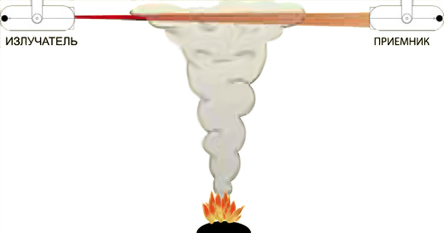
Linear smoke detectors have a design that differs significantly from that of a point fire detector. They consist of two elements (receiver and transmitter), the installation of which must be carried out on the walls before the ceiling, at a distance of 0.1 - 0.6 m from the level of the ceiling itself. It is also important to ensure that the optical beam generated by such a detector is not interrupted by any moving structures or elements of the floor itself (ledges, beams, etc.).
The use of such detectors is justified in rooms with high ceilings(up to 21 m), the length of which does not exceed 100 m. In this case, depending on the situation, two detector layouts are used: single tier and double tier.
Single tier layout used in rooms up to 12 m high, while the detectors are placed in such a way that the distance between parallel optical axes is no more than 9 m, and between the optical axis and the wall is no more than 4.5 m. It is also important to maintain a distance of at least 0.5 m from the optical axis to various surrounding objects (lamps, ledges, etc.).
Bunk layout used in rooms with a height of 12 to 21 m, while the detectors are placed in accordance with the table below in two tiers:
- first at a distance of at least 4 m from the floor level and 1.5 - 2 m from the upper level of the fire load;
- second at a distance of no more than 0.8 m from the ceiling.
It is also important to maintain a distance of at least 0.5 m from the optical axis to various surrounding objects (lamps, ledges, etc.).
Aspirating smoke detectors are used to control large areas. The use of one such sensor allows you to protect an area of up to 1000 m 2, which makes it possible to significantly save on communications and installation work. Such detectors are divided into three classes (A, B, C) depending on the level of sensitivity. Each level corresponds to a certain height of the air sampling tubes, which ultimately affects the final cost of the device.

Class A and B detectors have high sensitivity and are used in rooms with a ceiling height of more than 8 m. At the same time, air sampling pipes can be built into building structures or laid behind a false ceiling, with air sampling capillaries leading into the main space of the room. This solution allows, in addition to control large areas, use these detectors in rooms with high requirements for the interior.

When laying air sampling pipes with holes that come from the aspiration detector unit, it is worth observing all installation requirements that apply to conventional point smoke detectors.
Installation of thermal fire detectors
Such detectors are installed in rooms where the dominant sign of the onset of a fire is an increase in temperature. environment. Heat detectors, in addition to the main classification of detectors, have their own classification, according to which they are divided according to the principle of fire detection on: maximum (slow temperature increase to the maximum value) and differential (rapid temperature change), as well as by way of installation on:point and line. When installing such detectors, their sensitive elements should be placed under the ceiling of the monitored room, since warm air quickly rises and accumulates at the level of the ceiling.

When calculating the amount point thermal fire detectors and the place of their installation, all requirements must be observed SP 5.13130.2009 and follow the requirements of the table below:
The requirements of this table apply to the so-called square layout, when the detectors on the ceiling are placed in the shape of a square. This is the standard layout that is used in most cases. It should also be remembered that there is a scheme for installing detectors in a triangle, when the detectors form an equilateral triangle on the ceiling. Such a layout is more difficult to implement and is used only to protect large premises, for example, a closed parking lot or something like that.
Linear thermal fire detectors have a design that differs significantly from the design of a point fire detector. They are a special thermal cable, which is laid under the ceiling, or in direct contact with the fire load, while it is worth adhering to all the requirements and distances that are put forward for the installation of conventional point heat fire detectors. Also, such detectors are allowed to be used in warehouses with rack storage of products. In that case, for them maximum efficiency, sensitive elements (thermal cable) can be laid along the upper tier of racks.

Such detectors are installed in rooms where the dominant sign of the start of a fire is an open flame. Flame detectors, or as they are also called - light, in addition to the main classification of detectors, have their own classification, according to which they are divided according to the spectrum of electromagnetic radiation on: ultraviolet, infrared, multirange and visible spectrum detectors. According to the method of installation, they are point and can be mounted on the floor of the building, its walls, building structures or technological equipment that can catch fire during operation. When designing a system using flame detectors, it is especially important to take into account the initial stage of ignition, since if smoke is possible at this stage, then the detectors must be mounted at a distance of at least 0.8 m from the ceiling ( smoke collects before shutoff and may interfere with flame identification).
In accordance with current legislation, flame detectors must comply with the sensitivity class, according to which their range is determined. At the moment, there are 4 main classes:
1st class - up to 25 m;
2nd class - up to 17 m;
3rd class - up to 12 m;
4th class - up to 8 m.
It is also worth remembering that one zone must be controlled by at least two detectors, which are included in the circuit according to the logical “AND” scheme. It is allowed to install one fire detector in the event that the paragraph 3 of the requirements for the installation of fire detectors of this article.
Installation of gas fire detectors

Such detectors are installed in rooms where the dominant sign of the start of a fire is the accumulation of explosive gases, such as: CO 2 , CO or CH y . Gas detectors, in addition to the main classification of detectors, have their own classification, according to which they are divided according to the level of sensitivity to CO for 2 classes:
1st class - 20-40ppm;
2nd grade - 41-80ppm.
Installation of such detectors is carried out in accordance with the factory instructions and in accordance with the requirements of the table below:
Installation of combined fire detectors

Such detectors are used in cases where the dominant initial sign of fire is unknown or there may be several such signs, for example, smoke and high heat generation. Such a detector, visually, is practically no different from a conventional smoke detector, but contains a combination of several sensors, most often these are smoke and heat sensors.
To date, a new class of combined fire detectors has appeared - multisensory, which respond to all fire initiating factors (smoke, heat, carbon monoxide (CO) and open flames). They have high noise immunity, which helps to avoid false alarms of the system and respond to any of the signs of a fire. Installation of such detectors is carried out in accordance with the factory instructions and in accordance with the requirements of the table below:
Installation of such detectors is carried out on the evacuation routes from the protected object, on the walls, at a height of approximately 1.5 m from the floor level. The main task of such a detector is to manually start the fire alarm system by a person who saw a fire at the facility. When installing, please follow the instructions fire regulations, according to which, the distance between adjacent detectors in the building should not exceed 50 m and 150 m on the street. Also, special attention should be paid to ensure that access to the detector is not obstructed by foreign objects, and the installation site has sufficient lighting for its timely detection.